check

check

check

check
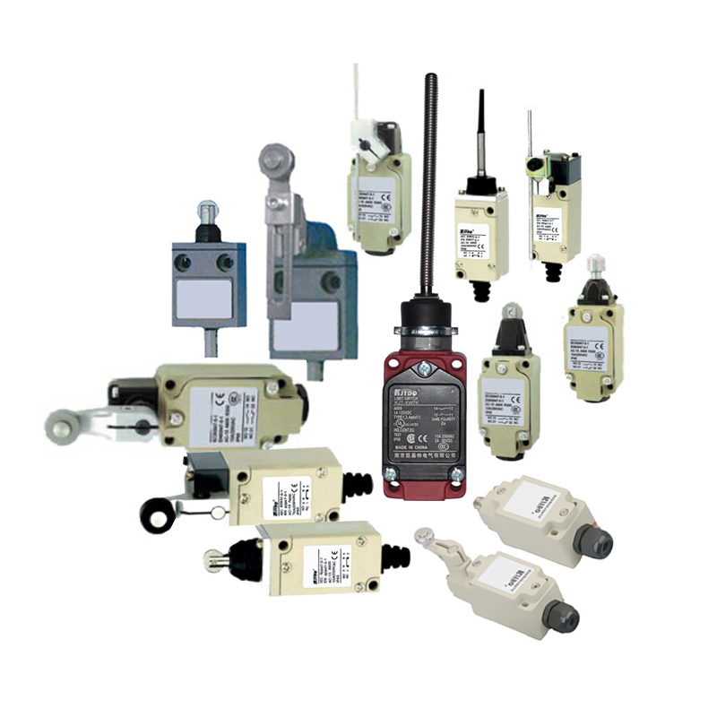
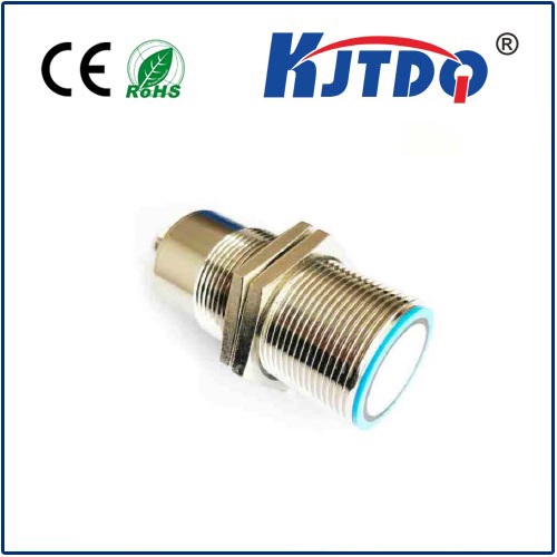
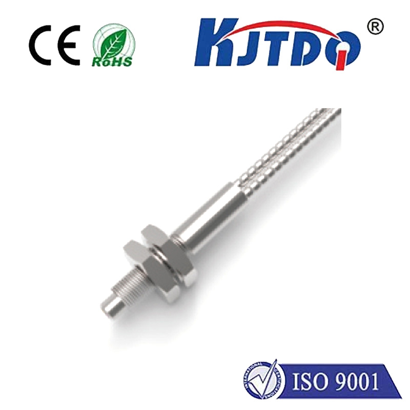
The function of the limit switch (limit sensor) is to detect the position of the piston rod during the movement of the servo electric cylinder, and to stop the movement when it reaches the set upper or lower limit position. It plays the role of overtravel protection to avoid possible mechanical damage and personal injury caused by the electric cylinder exceeding the predetermined range.
When installing the limit switch of the servo electric cylinder, the upper limit installation method is as follows:
Correctly connect the electric cylinder and servo motor, and select the jog mode. It is recommended to use a motor rated power below 150W.
First, identify the working direction of the electric cylinder and extend the piston rod by inching.
Accurately measure the extension length of the piston rod and determine the maximum position of the piston rod according to the design drawing.
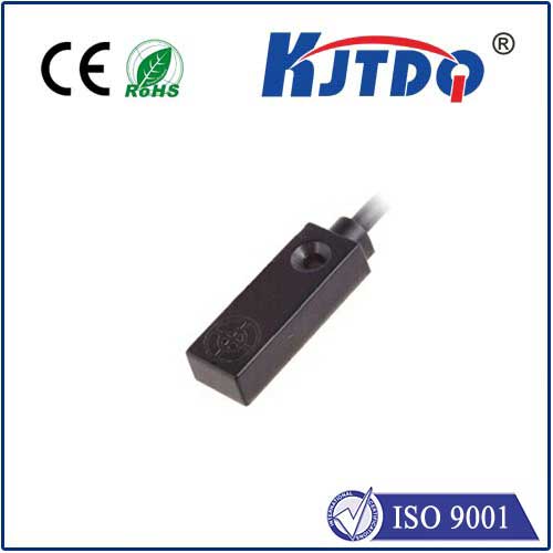
Fix the magnetic sensor on the mounting groove on the surface of the cylinder, and turn on the magnetic induction switching power supply.
Slowly adjust the sensor to the upper limit position.
Tighten the screws and secure the magnetic sensor.
The lower limit installation method is as follows:
After installing the motor control section, insert the servo motor and set it in inching mode.
It is recommended to use a speed ratio of 150 rpm. Inching to retract the piston rod to its lowest end.
Install the magnetic sensor in the groove on the surface of the cylinder and connect the power supply.
Immediately move the motion sensor to the bottom and gradually move it up from the bottom.
When the sensor light flashes, it indicates that the lower limit position has been reached.
