The forward and reverse dual-channel speed sensor has no contact with the measured gear, has no wear, and is easy to install. The output waveform is a square wave with a duty cycle of about 50%. The sensor has good low-frequency and high-frequency characteristics. The low frequency can be as high as 0Hz, which can be used for zero-speed measurement of rotating machinery. Since the sensor can give two speed signals with a certain phase difference, it can distinguish forward and reverse rotation; the high frequency can be as high as 20KHz, which can meet the needs of most industries. High-speed measurement requirements in the field.

| Product Paramenters |
| Working power supply | Ub=15VDC±30% (8V~28V) |
| Power consumption current | ≤35mA |
| Operating temperature | -40℃~125℃(head) |
| Vibration resistance | Vibration (10Hz~2KHz) 30g, shock 100g |
| Sealing | IP6813. |
| Power polarity protection | YES |
| Output short circuit protection | YES |
| Dielectric strength | 1000V 50Hz, 1min (channel and shell) |
The reverse rotation speed sensor is used to detect the rotation speed and linear speed of the wheel shaft.
Through calculation and processing, the speed of the measured object can also be obtained.
The sensor has good low-frequency and high-frequency characteristics.
The low frequency can be as low as 0Hz, which is used for the zero speed of rotating machinery, and as high as 20KHz,
which can meet the high speed measurement requirements of most industrial fields.
Since YD69 can provide two speed signals with a certain phase difference, it can distinguish forward and reverse rotations.
It is easy to install, has no contact with the measuring gear, and has no wear.
The output waveform is a square wave with a duty cycle of about 50%.
It has a wide speed measuring range, wide temperature adaptability, strong vibration resistance,
and has power supply polarity protection and output short-circuit protection.
1. Sensor installation
● The inductor to be measured is a magnetic conductor with teeth or grooves on it.
Recommendation: speed measuring gear module ≥1.7, material is magnetically permeable low carbon steel
Note: Non-standard teeth or grooves with different widths from the flat surface will cause changes in the waveform width ratio.
● Installation gap: 0.5-2mm, typical value is 1.0mm
Note: Depends on the vibration condition of the component under test
2. Sensor output characteristics
● Frequency response characteristics: 0~20kHz
●Number of output channels: dual channels
● Output waveform: square wave, rising and falling edge time 12μs±40%
● Output amplitude: high level: U-0.7 (U: power supply voltage), low level: < 0.1V
●Pulse duty cycle: 50%±25%
● Phase difference: 90±30° (the first channel leads)
Note: It depends on the installation method and the rotation direction of the rotating part.
This parameter is applicable to the installation method shown in Figure 4 of this manual.
● Load capacity: ±20mA (suitable for large)
● Output impedance: <47Ω
● Power supply voltage: Ub=+24VDC (5V~26V)
● Power consumption current: ≤35mA
● Working temperature: -40℃~+125℃
● Vibration resistance: vibration (10Hz~2KHz) 30g, impact 100g
● Sealing: IP68
●Power polarity protection: yes
● Output short circuit protection: yes
● Dielectric strength: 1000V 50Hz, 1min (channel and shell)
● Shell material: stainless steel 304 (other materials can be used according to user requirements)
1. Principle of speed measurement
When the speed measuring gear rotates,
the sensor will generate a square wave signal with frequency f (Hz) = n×m/60 (n is the rotation speed,
P is the number of gear teeth) for the locomotive electronic control system to sample
and detect the locomotive speed and diesel engine speed. .
The induction body must be a magnetic conductor, which can be a groove, or a protruding screw or gear.
The application of this sensor to measure rotation speed involves the following parameters:
m—the number of inductors on the rotating magnet under test
n—speed
f—input signal frequency
s—set instrument coefficient (depending on the characteristics of the speed measuring instrument.
Some speed measuring instruments directly set the number of teeth.
Please select the instrument coefficient according to the instruction manual of the selected speed measuring instrument)
The relationship is as follows:
n = s f = 60 f / m
After the number of sensing bodies of a measurement system is determined, the instrument setting coefficient has been determined.
The coefficient of each channel is determined according to the number of sensing bodies corresponding to the sensor of each channel.
For example, when measuring the rotation speed of a rotating shaft, there is a 30-tooth tone wheel on the shaft,
which is equivalent to the number of teeth of the induction body Z = 30.
Then the frequency output by the sensor per channel is f = (30/60)n, and the rotation speed n = 2f.
That is, the measured frequency number must be multiplied by 2 to equal the actual speed.
Set the speed measuring instrument coefficient at 2, that is, s = 2, then the actual speed of the rotor can be directly displayed.
Similarly, if 2 signals are generated per revolution, set the coefficient s = 30, and so on.
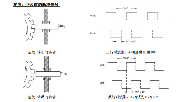
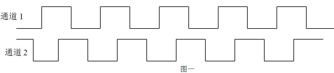
3. Measurement principle of forward and reverse discrimination
The Hall dual-channel sensor can be used to easily determine forward and reverse rotation.
Install according to the application example in the fourth section of this manual.
When the rotation direction is defined as forward rotation as shown in Figure 4,
the output waveform is channel 1 leading channel 2 by 90 degrees.
The waveform diagram is as follows:
When the rotation direction is opposite to the direction shown in Figure 4,
the channel 2 waveform will lead the channel 1 waveform by 90 degrees.
The waveform diagram is as follows:
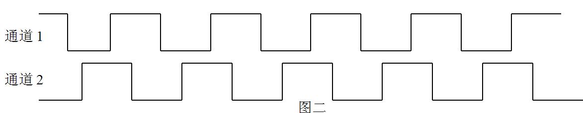
As can be seen from the above figure,
forward and reverse can be distinguished by phase identification of the waveforms of channels 1 and 2.