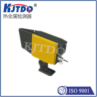
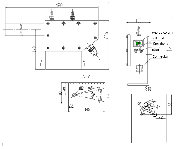
When the detector is installed on site, the distance can be set according to the field of view and the type of material returned, and the detector can be aligned by visual inspection.
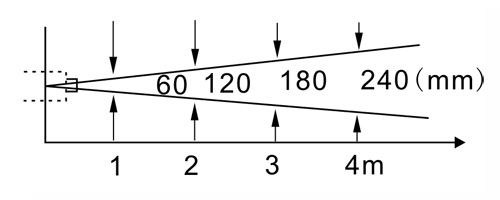
HMD hot metal detectors all have a certain field of view. For any kind of HMD, it should be ensured that the movement range of the measured object is within the field of view of the HMD.
The HMD detection field of view range and setting distance reference table is as shown below. If there are special requirements for the field of view range, it can be customized.

■ Light column:
In order to make the HMD suitable for working under various conditions, it is equipped with four kinds of aperture plates (Φ2, Φ4, Φ8, Φ16), which can be used to change the size of the field of view.
■ Cooling interface:
The cooling interface is used to pass cooling water. When the temperature around the detector installation location reaches above 70°C, water cooling is required, and the water pressure is 0.3MPa.
■Purge interface:
When there is water vapor or smoke in the detector's field of view, the sensitivity of the detector will decrease, so you should be careful when setting it up. In order to prevent this phenomenon, 0.3MPa compressed air should be added to the purge port of the dustproof tube.
■ Wiring:
a. The cables from the detector to the electrical room should use shielded cables as much as possible.
b. The cable connecting the detector to the control room must be within 200m and not too long.
c. Safety protection measures must be taken when the cable passes through a higher temperature zone.
■ Level output:
The level output uses NPN/PNP transistor push-pull output, as shown in Figure 10, but only one load can be connected at the same time.
There are two types of load allowed for level output: resistive load and inductive load. The suitable large load current that can be provided is 100mA.
■Contact output:
The cooling interface is used to pass cooling water. When the temperature around the detector installation location reaches above 70°C, water cooling is required, and the water pressure is 0.3MPa.
The output stage of the contact output is the contact of the relay. When using it, be careful not to let the maximum operating current of the load exceed the allowable current of the contact capacity, and the power of the load must not exceed the contact capacity.
There are two ways of contact work: DC mode and AC mode. There are no restrictions on the nature of the load in the two methods. Resistive loads or inductive loads can be connected. However, the use of these two methods is slightly different. As shown in Figure 11, it is the DC wiring method. Figure 12 is the AC wiring method.
When used in DC mode, for inductive loads, a freewheeling diode should be added as shown in the dotted line in Figure 10. The freewheeling diode should be 0.5 A, which is more than three times the load voltage.
When working in AC mode, for inductive loads, R and C absorption circuits should be added as shown in Figure 12.
