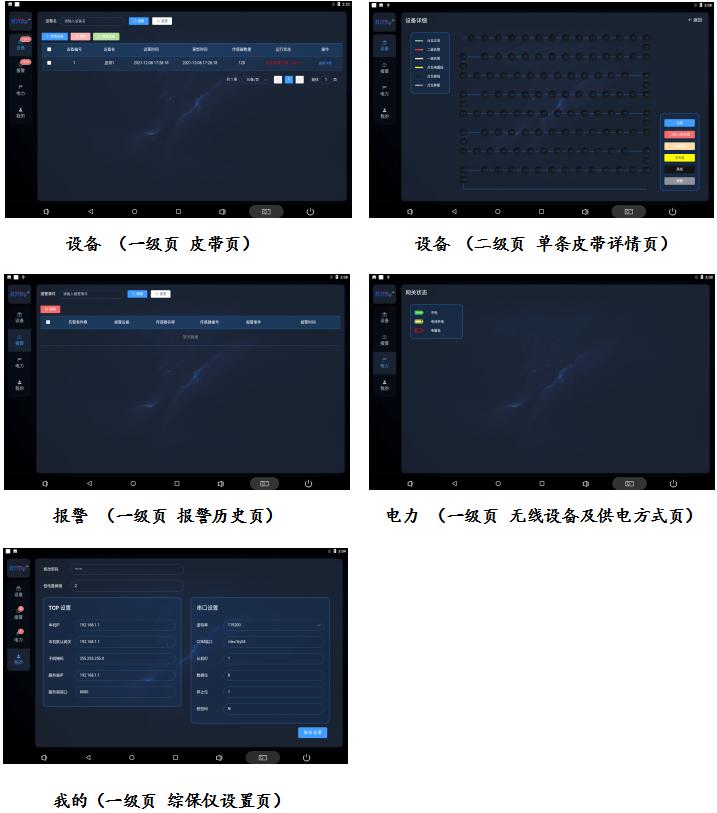
The display interface has a left-right horizontal
layout, with the menu bar on the left and the
corresponding menu first-level page on the right.
1. Single page dynamic description
equipment
On the equipment page, you can add or delete configurations to view the number and name of the belts,
the number and operating status of the
protective devices on the belts.
The running status bar displays the number of point anomalies in real time.
Click View Details to enter the details page of this belt.
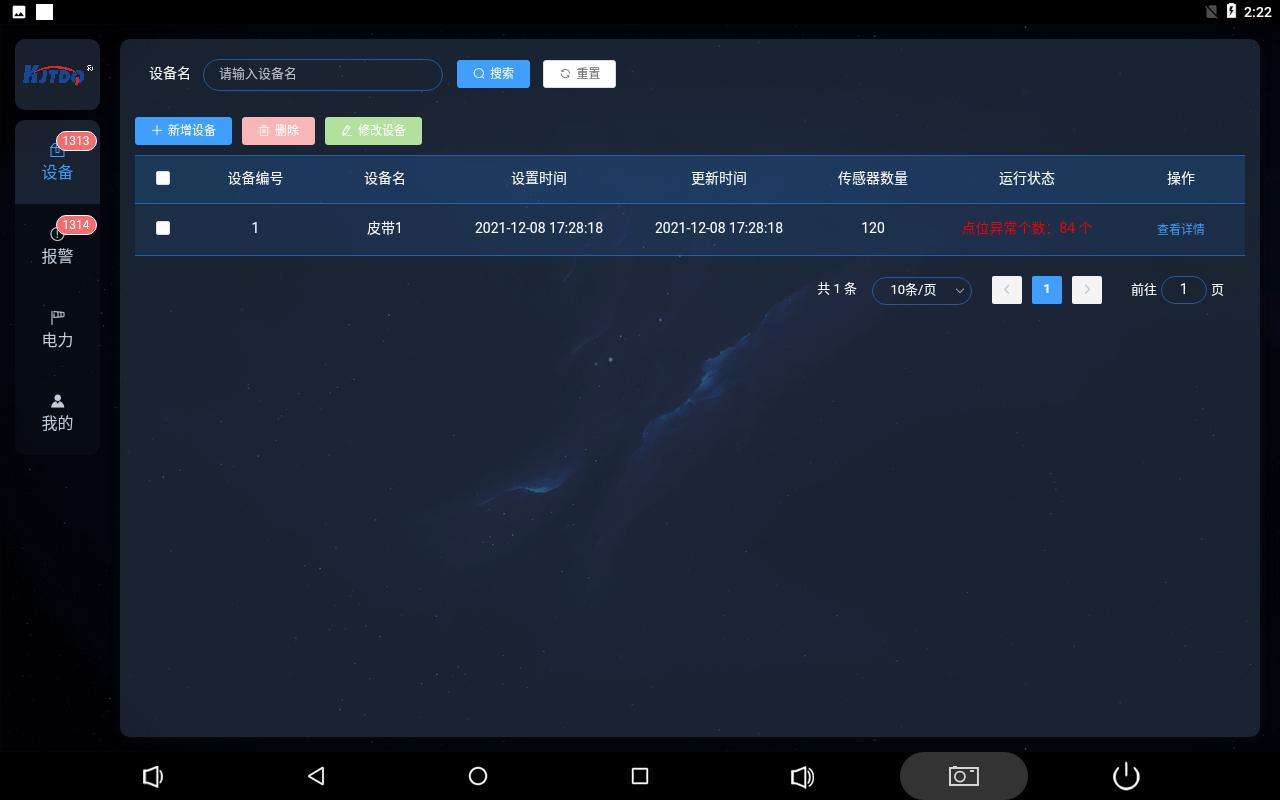
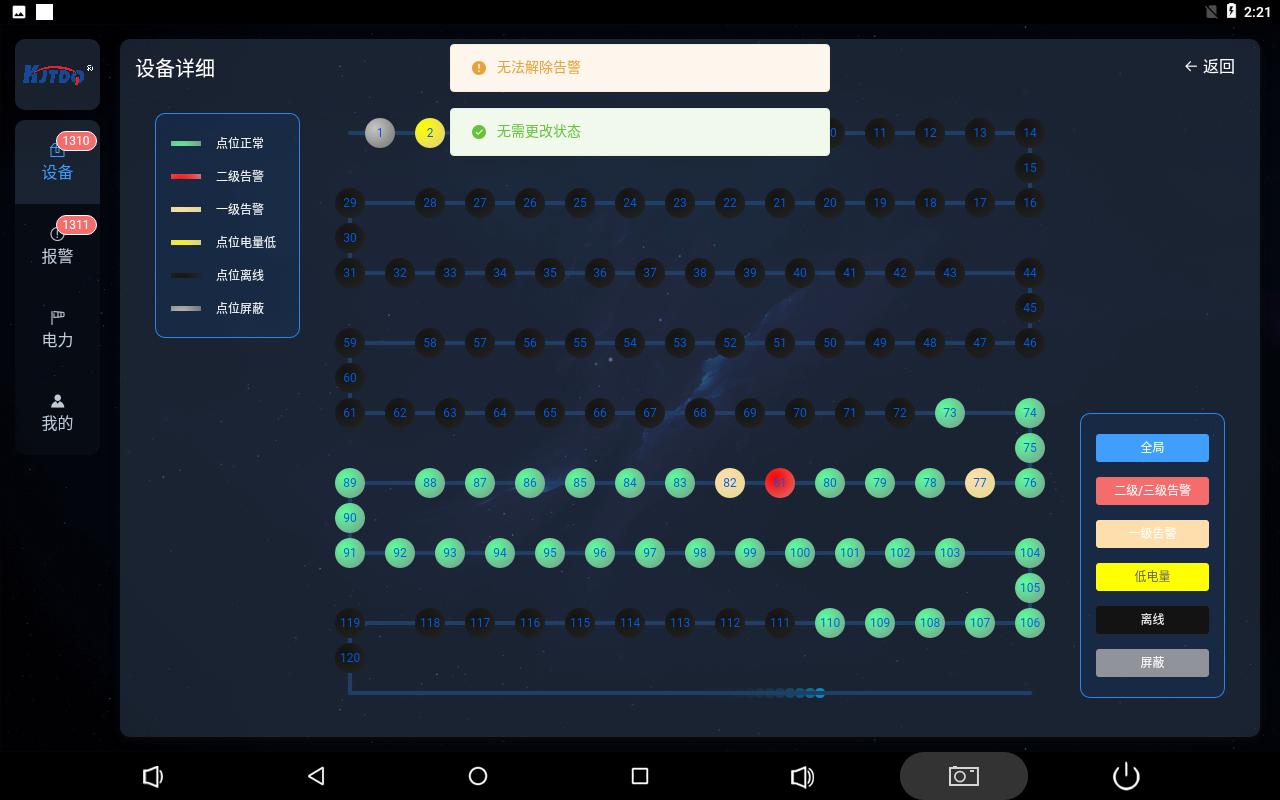
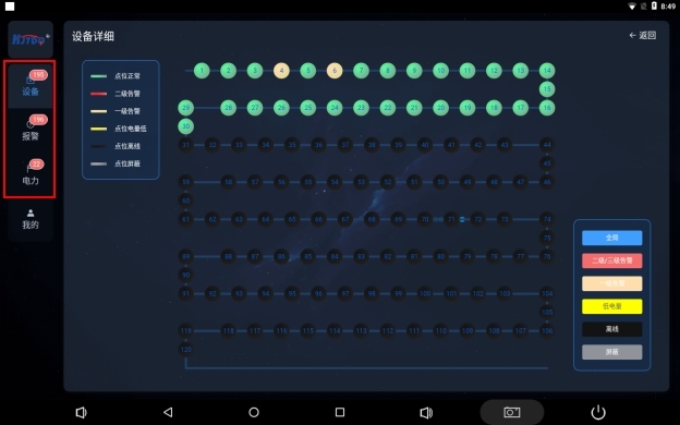
Device details page
The device details page displays the current status link diagram of the belt protection device in real time,
which is divided into 6 color displays, which respectively represent the protection device is normal, the protection
device has a second-level alarm, the protection device has a first-level alarm, the protection device has low power,
and the protection device Offline, the protection device blocks six states.
When the protection device is in multiple states, the display status display priority is
Protective device shielding
Protection device level two alarm
Protection device level one alarm
Protection device offline
Protection device battery is low
Protection device is normal
The circle represents the protection device, and the number in the circle represents the ID number of the protection device.
There are 6 colored buttons in the lower right corner. Click the global button to display the status of all circles normally.
For the other 5 buttons, click the corresponding button, and all the circles of the corresponding status on the screen will flash.
The priority of the flashing display is the same as above.
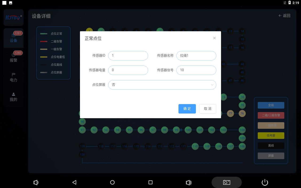
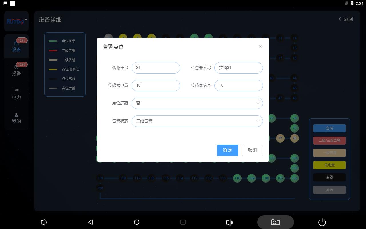
Click the circle to pop up the detailed information of the corresponding protection device, and you can set the shielding status of the protection
device and manually release the secondary alarm status.
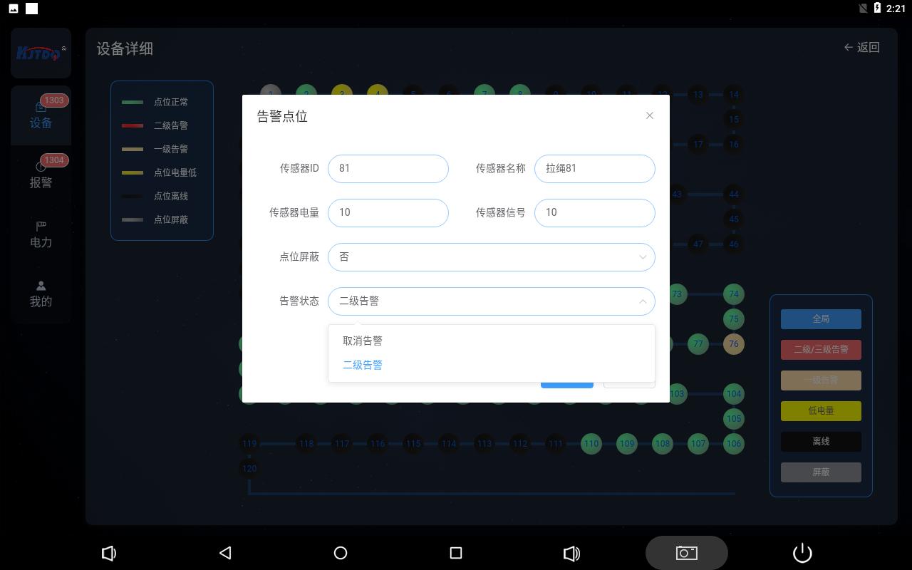
Click the drop-down menu in the box after the corresponding operation name, select the option, and click Confirm to complete the operation.
The secondary alarm status requires the on-site protection device to successfully remove the secondary alarm. Click to remove it to be effective,
otherwise it will be invalid.
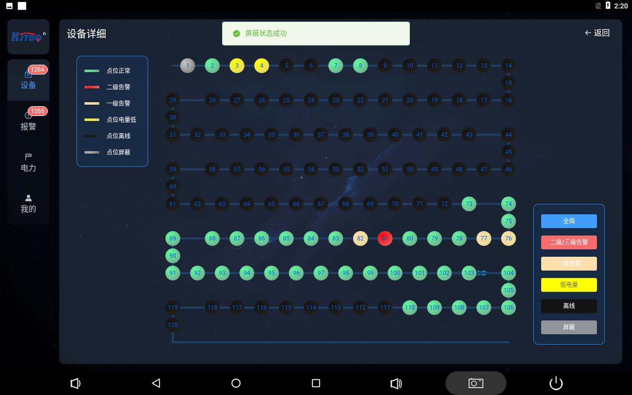
设置成功或者失败页面上方都有相应弹框弹出提示,设置成功后,链路图上的圆圈会变为设置状态。
报警
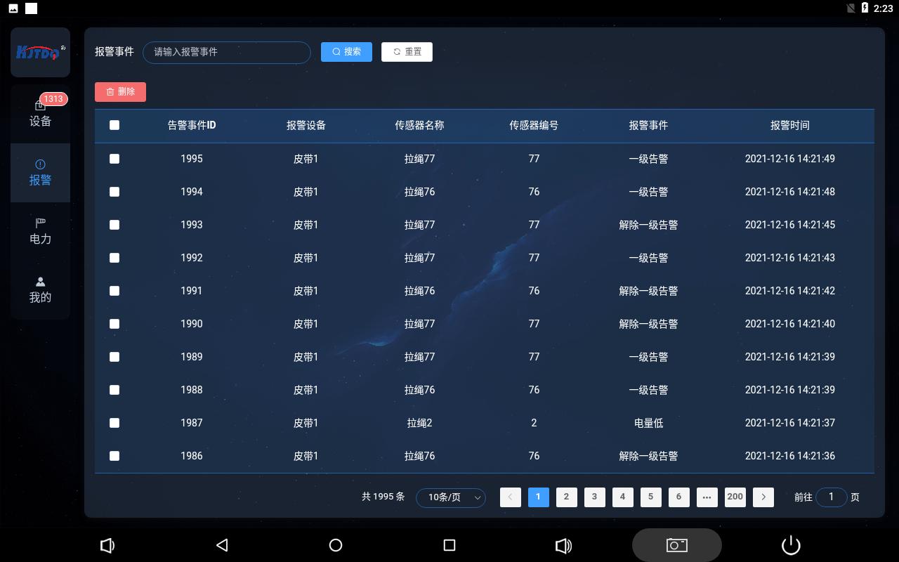
The alarm page refreshes and records alarm events in real time, recording the alarm information and occurrence time of the protection
device corresponding to the corresponding address number on the belt. The information recorded in the alarm is the protection device
online, offline, low battery, first-level, second-level alarm, first-level alarm , the second level alarm is lifted.
The alarm events have been arranged in reverse order, that is, the latest alarm events are displayed, and the pages are displayed, with ten
items per page. Alarm events can be deleted with administrator privileges, and ordinary personnel cannot perform this operation.
electricity
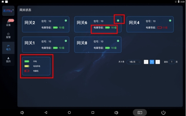
The power page shows the online monitoring of wireless repeaters and wireless smart gateways in the entire wireless system. The gateway design
is based on the power supply method required by the owner. The power supply composition can be freely combined in three modes: mains power
supply, battery power supply, and photovoltaic power supply. and automatic switching.
The green circle in the red box on the picture indicates that the device is normally online, and black when abnormal.
In the mains power state, there is a battery-shaped icon, with a green level 10 display when fully charged. When the battery is powered, the
battery power will be detected. 10-level display, the power detection display interval is 1 level, that is, 0, 1, 2, 3, 4, 5, 6, 7, 8, 9, 10 feedback.
mine
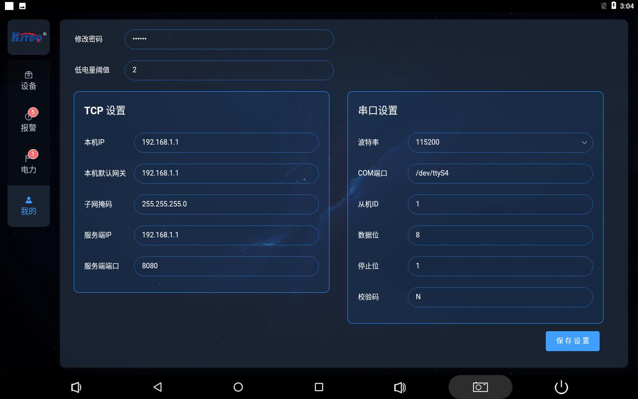
我的页面为综保仪设置页面,需要管理员权限进行进入配置管理员密码和本机参数。
When a status change or alarm occurs on any page, the menu page options will increase the corner push function and the number of events
during the unviewed period, and will automatically disappear after a click.
1. Serial port
UART2 (TTL level); UART3 and UART4 have been converted to RS232 level and treated with anti-static treatment. In addition, UART4 is an
RS485 interface (automatic flow control), the RS232 serial port is led out through a DB9 male connector, and 485 is a 4pin Phoenix terminal.
2.USB
Integrated 7 USB Host interfaces (1 Type-A_HOST interface, 1 Type-A_OTG interface, 5 built-in expansion USB2.0) for external high-definition
USB, camera, U disk, keyboard, mouse and other devices.
3. Network port
The LAN interface is a 100M adaptive Ethernet interface, which is led out through RJ45. If you want to use Android's Ethernet function, the user
needs to plug the network cable into the LAN interface and then turn on the Ethernet function through settings. The default Ethernet uses DHCP
to allocate IP. If you want to manually configure the IP address, you can configure it in the advanced settings.
device installation
Before powering on, install the antenna first, take out the regulated power supply box and connect it to the PWR, pass the communication network
cable through the matching network cable waterproof head and connect it to the ETH, press ON/OFF
Power button, STA flashes quickly and then slowly, indicating normal operation;
The smart gateway and wireless transmitter are paired and installed. The pairing process has been completed by default before leaving the factory.
The device ID is affixed to the surface of the product and installed according to the corresponding point table;
The smart gateway is connected to the host computer through a network cable for data transmission, and the transmission protocol is MODBUS
TCP.
1. Serial port
UART2 (TTL level); UART3 and UART4 have been converted to RS232 level and treated with anti-static treatment. In addition, UART4 is an RS485
interface (automatic flow control), the RS232 serial port is led out through a DB9 male connector, and 485 is a 4pin Phoenix terminal.
2.USB
Integrated 7 USB Host interfaces (1 Type-A_HOST interface, 1 Type-A_OTG interface, 5 built-in expansion USB2.0) for external high-definition USB,
camera, U disk, keyboard, mouse and other devices.
3. Network port
The LAN interface is a 100M adaptive Ethernet interface, which is led out through RJ45. If you want to use Android's Ethernet function, the user
needs to plug the network cable into the LAN interface and then turn on the Ethernet function through settings. The default Ethernet uses DHCP
to allocate IP. If you want to manually configure the IP address, you can configure it in the advanced settings.
device installation
Before powering on, install the antenna first, take out the regulated power supply box and connect it to the PWR, pass the communication network
cable through the matching network cable waterproof head and connect it to the ETH, press ON/OFF
Power button, STA flashes quickly and then slowly, indicating normal operation;
The smart gateway and wireless transmitter are paired and installed. The pairing process has been completed by default before leaving the factory.
The device ID is affixed to the surface of the product and installed according to the corresponding point table;
The smart gateway is connected to the host computer through a network cable for data transmission, and the transmission protocol is MODBUS
TCP.