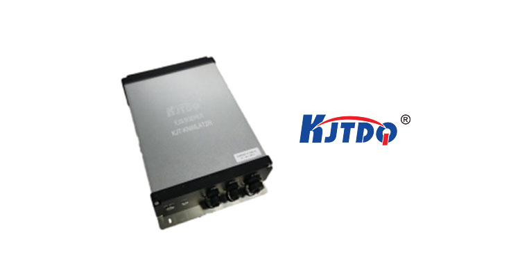
Wireless intelligent gateway * 1
3dBi high gain fiberglass antenna * 2


![]()
Model | KJT-KNWLAT2RIRL | |||
| Protocol standards | LoRa Private Network Protocol | |||
| Frequency range | 470~510MHz LoRa | |||
| Maximum link budget | 169dB | |||
| Maximum transmission power | 27dBm | |||
| Polarization mode | Monopolarization; Vertical polarization | |||
| Transmission rate receiving sensitivity (dBm) 2400bps -126dBm Sensitivity 800bps -130dBm300bps -142dBm | ||||
| Networking method | Star shaped | |||
| Suggested transmission distance | 20-1000M | |||
| Management | ||||
| Management style | Support Chinese/English management, configure restart free; Support cloud management | |||
| Reset | Hardware | Support | ||
| Software | Support | |||
| Function | ||||
| Working mode | P2P-S, M2P, etc. | |||
| Input configuration | Supports RS485 serial port and Ethernet interface | |||
| Communication protocol | MODBUS | |||
| Signal lamp | Two color waterproof signal light | |||
| Safety | ||||
| Wireless encryption | CPC verification AES128 | |||
| Hardware | ||||
| CPU | Industrial grade MCU | |||
| Memory | FLASH | 32MB | ||
| SRAM | 2M | |||
| Expansion card (optional) | Support | |||
| Dominant frequency | 400MHz | |||
| Interface | |||
| Connecting port | Number of connectors | 3 | |
| Connector properties | 1 waterproof DC interface, 1 waterproof RJ45 interface, and 1 waterproof RS485 interface | ||
| Antenna | Antenna interface | N-type female head with 1 transmission and 1 reception (default) | |
| N-type female head, 1-way relay, 1-way 4G (optional) | |||
| Antenna gain | 3dBi | ||
| Antenna angle | Vertical polarized omnidirectional antenna | ||
| Power supply | |||
| Power supply method: Power supply | DC10V-30V Recommended 12Vor24V | ||
| Work environment and characteristics | |||
| Surge protection | Common mode 4Kv/differential mode 2Kv | ||
| Humidity (non condensing) | ≤ 95% (non condensing) | ||
| Operation temperature | -40~75℃ | ||
| Storage temperature | -40~80℃ | ||
| Characteristic | Number of uplink receiving channels | 2-way (supports 2-way parallel reception) | |
| Number of downlink transmission lanes | 1 way | ||
| Number of relay channels | 1 way | ||
| Size | L*W*H(mm) | 250*200*75 | |
| Working current | Full load working current | < 1.5A @12V | |
| Normal operating current | < 600mA @12V | ||
| Idle working current | <70mA @12V | ||
![]()
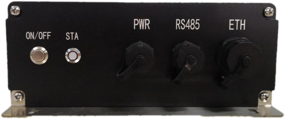
| ON/OFF: | Operation button switch | STA: | Running status indicator light |
| PWR: | DC24V power interface | RS485: | 485 serial communication port |
| ETH: | Ethernet communication port |
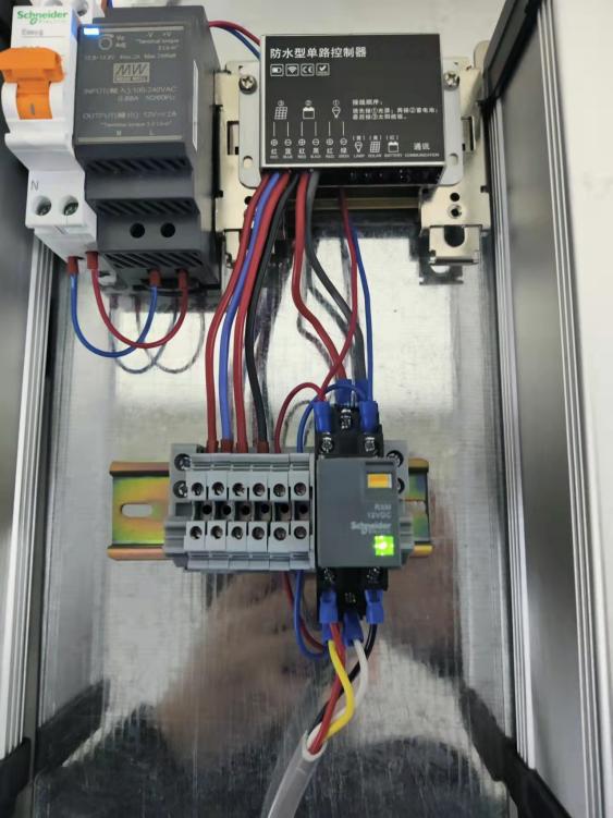
1. Equipment installation
(1) Equipment installation and 304 stainless steel rainproof power supply box, with priority given to installing antennas before power on;
(2) Connect the PWR quick connector and press the ON/OFF power button;
(3) The STA green light flashes rapidly and then slowly, indicating normal operation, while the red light flashes indicating interruption of the wireless relay link;
(4) Wireless repeater, wireless rope switch, and wireless host are paired and installed. The pairing program is completed by default before leaving the factory. The device ID is attached to the surface of the product and installed according to the corresponding point table;
2. Matching point table
| Wireless rope switch | Wireless Repeater | Wireless Host | |
| 1 | ID1~ID16 | ID1 | |
| 2 | ID17~ID48 | ID2/ID3 | |
| 3 | ID49~ID76 | ID4/ID5 | |
| 4 | ID77~ID98 | ID6/ID7 | |
| 5 | ID77~ID98 | ID8 |
Relay link table
| Wireless Host | Wireless Repeater | Wireless Repeater | Wireless Repeater | Wireless Host | Wireless Host |
| ID1 | ID2/ID3 | ID4/ID5 | ID6/ID7 | ID8 | ID9 |
Power supply instructions
(1) The repeater is powered by two methods: on-site power supply and solar cell power supply
(2) The on-site power supply is the main one, and it will automatically switch to solar power supply after the on-site power outage
(3) Even without sunlight, the battery can provide 200 hours of electricity
(4) The power switching module has been connected and installed before leaving the factory
(5) The air switch is the main switch
(6) The relay light is on for on-site power supply, and off for solar power supply
(7) At that time, when solar energy was used for power supply, the equipment reported the current power supply method and battery level situation
(8) The intelligent gateway is connected to the upper computer through a network cable for data transmission, and the transmission protocol is MODBUS TCP.