
check

check

check

check
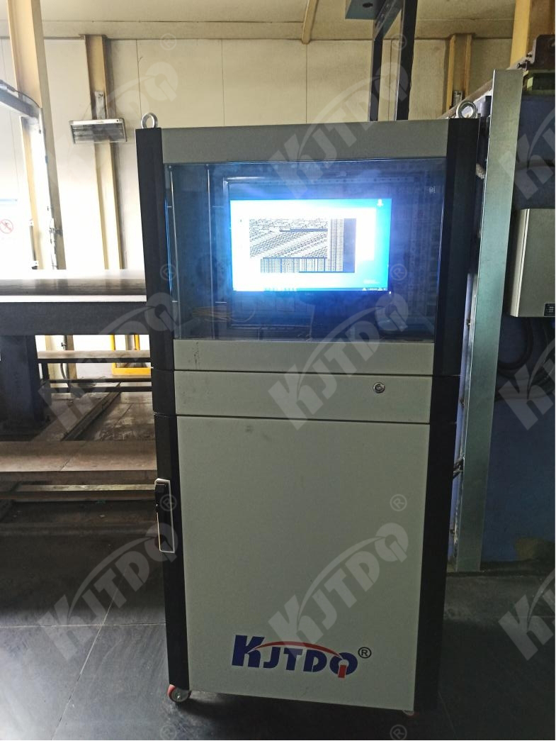
Based on customer needs and after on-site technical assessment, Kejit provides customers with steel coil testing and related technical services for material luminescence demonstration. The software system of this project adopts the company's independently developed strip surface detection technology, hole and edge crack lighting technology and online measurement and detection technology.
This system is based on machine vision technology and features high-speed, high-precision new photosensitive technology.
It adopts high-speed customized LED parallel light source and unique heat dissipation technology to ensure high brightness, high stability, long service life and simple maintenance.
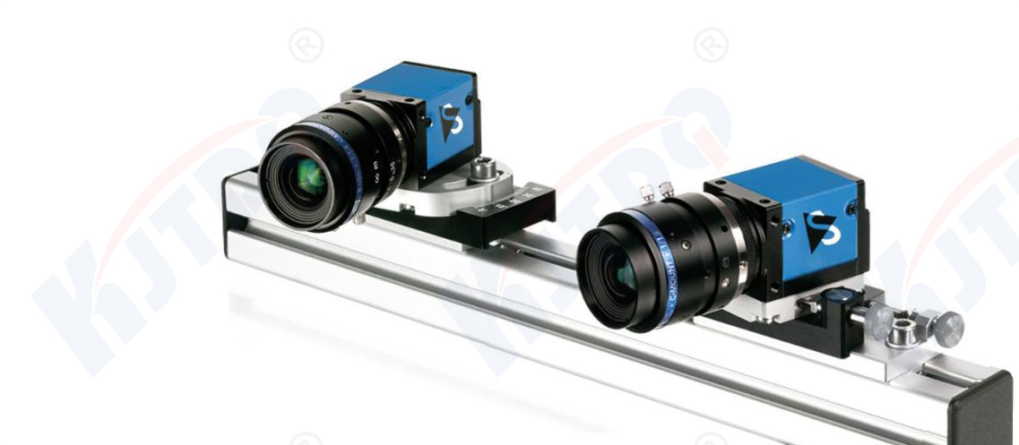
It adopts high-performance COMS digital camera and optical technology to ensure the reliability of high-resolution and high-definition image storage and information transmission.
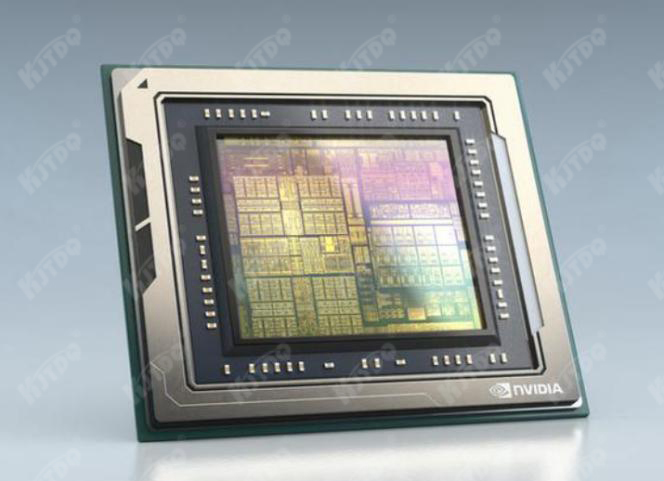
A specially designed GPU module is used to ensure high-quality detection and stable operation of the system.
Optional multi-function detection, full-length and full-width detection. --》Full-length, full-width multifunctional detection range
This vision module adopts self-learning technology in the direction of artificial intelligence (deep learning CV). The samples continuously learn new process requirements quickly by themselves, and cooperate with the existing image library to quickly and conveniently add issues that need to be traced.
This system uses a self-learning system that can continuously iterate to achieve the effect of becoming more accurate and smarter the more it is used. The sample database can reach tens of millions, with unlimited scalability.
Traceability visualization; convenient for customers to query historical records quickly and conveniently; search based on rules; supports offline client export data, multi-terminal simultaneous query and other functions.
The real-time multi-terminal online viewing and early warning module facilitates Party A to control the on-site situation at the first time and handle it in a timely manner.
Through the high degree of cooperation between the software and hardware of this system, it can meet the strict testing requirements of the metal industry, improve the yield rate, and avoid returns and complaints caused by defects caused by unqualified products leaving the factory.
It adopts deep learning, lighting parallel light, high-speed GIGE, CAMELINK, high-speed synchronization device, distributed system expandability, and a visual solution combined with optical technology.
Strip detection range: 900mm-2000mm
Maximum detection speed: 600m/min
Thickness: 2.0mm-12.0mm
Steel coil vibration: less than ±10mm
Detect and classify defect categories: peeling, inclusions, scratches, indentations, stains, oxygen spots, peak-like iron oxide scale, edge damage, holes, edge cracks, waist folds, lack of pickling, parking spots, watermarks, severe color difference wait;
System operation rate: ≥99.8%;
Defect detection rate: ≥95%;
Defect classification accuracy: ≥85%
The large roller in front of the inspection platform.
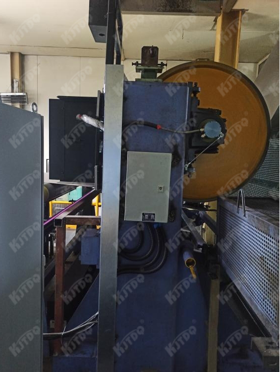
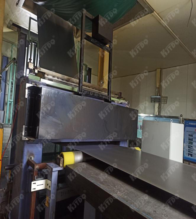
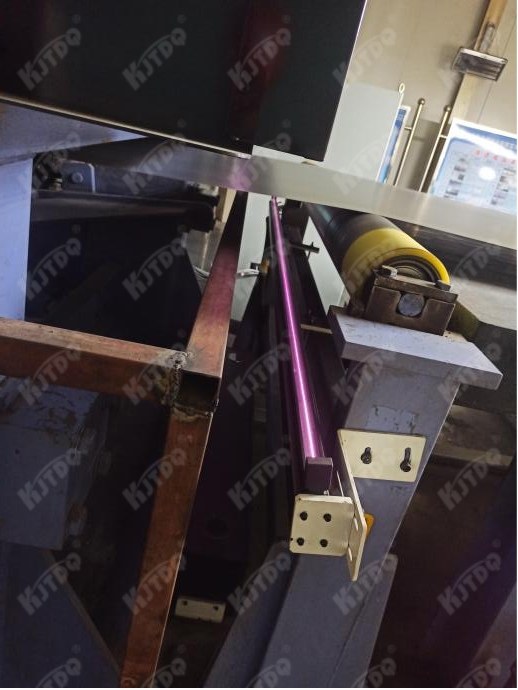
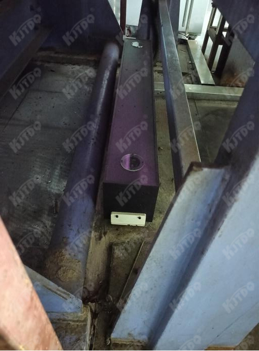
6.Installation location of cold rolling surface defect detector and high-precision multi-function detector
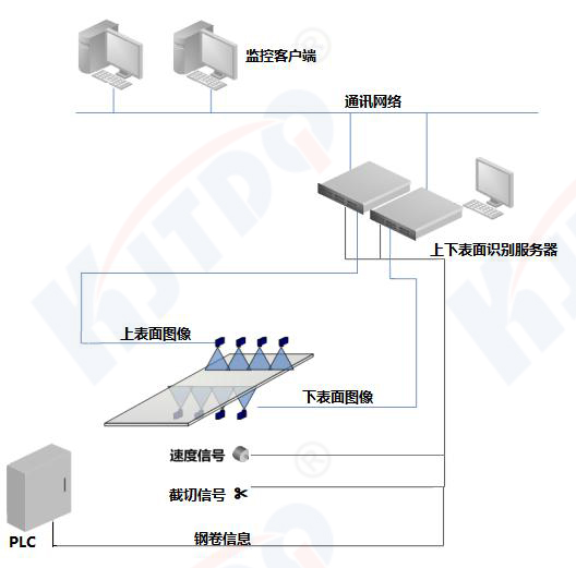
(1) The surface inspection bright field adopts a parallel white light reflection mechanism, and with the optional color CCD line scan camera (color steel), various colored defect features and color spots can be photographed. The ordinary cover can be used with high-sensitivity CCD black and white line scanning for more sensitivity.
(2) The optional hole edge crack module system uses edge cracks and the light transmittance of holes to detect actual defects from the physical level.
(3) The entire system adopts a distributed architecture, and the asynchronous hardware architecture implements a large amount of computing work in machine vision, and uses self-learning to extract defects.
(4) The entire system communication adopts low-latency, verified, and self-designed UDP communication mechanism to ensure rapid data synchronization and high throughput.
(5) The distributed system architecture can horizontally expand more storage space; provide more parallel computing power; improve camera accuracy, etc. Facilitate subsequent enterprise upgrades.
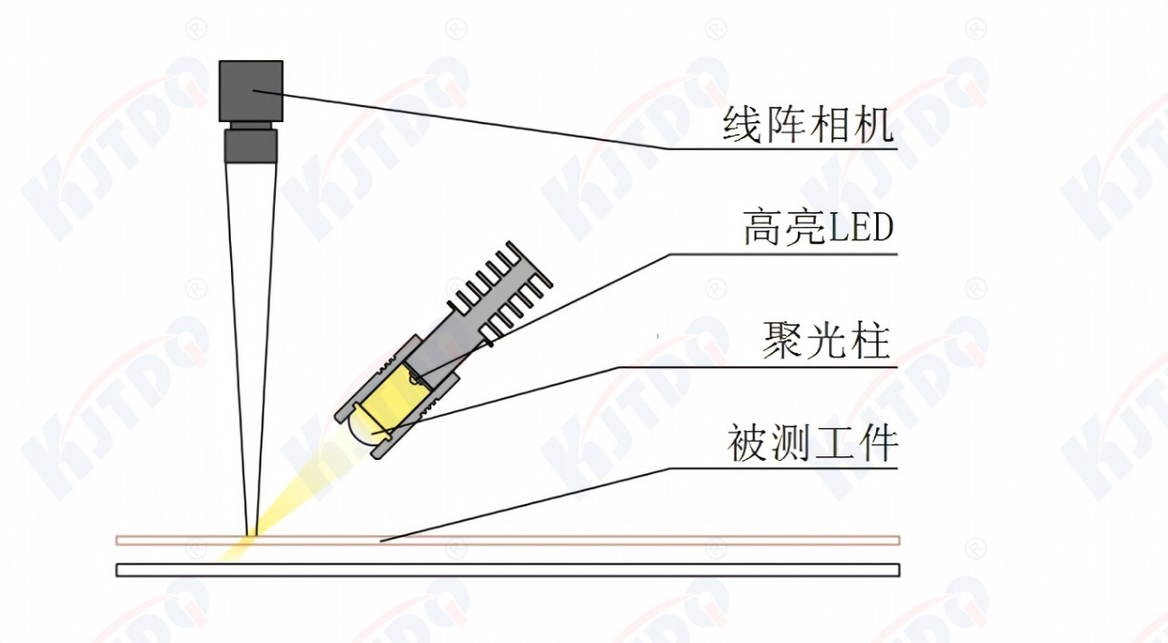
(1) Optical path design table inspection defect detection system
The incident angle of the light source and the shooting angle of the camera are called optical paths. The signal strengths of different defects under different optical paths are different. Since the optical path design cannot be changed once the equipment is installed, the accuracy of the optical path design determines the defect detection The signal intensity of different defects under different optical paths is different, so it is necessary to design appropriate optical paths for different applications and defect morphologies.
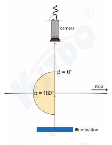
Optical path design multi-function detector system
For penetrating defects, the transmitted light path is the best imaging solution. Since the harmless part is opaque and appears black, the defective part is transparent and has a higher grayscale, thus forming the maximum difference between the target and the background in the image. , easy for subsequent image processing and recognition.
The camera and the light source are opposite each other at 180 degrees, and the light source adopts a scattering method to ensure that the light can penetrate the hole defects to the maximum extent and reach the photosensitive element.
At the same time, due to the diffraction effect of light, the transmission light path can also appropriately amplify the light spot, which plays a role in improving detection accuracy.
(3)resolution design
High-speed industrial cameras image by arranging pixels. Assume that the CMOS of a camera is composed of 30 horizontal pixels * 30 vertical pixels. Then the physical resolution of the camera is 900 pixels, which is the image formed by it. The maximum is 30*30 pixels. If the actual space covered by this image is 3mm horizontally and 3mm vertically, then define the detection system: system horizontal resolution=3mm/30pixel=0.1mm/pixel, system vertical resolution=3mm/30pixel=0.1mm/pixel. The image of a defect or target is also composed of pixels. If the defect occupies too few pixels, the software algorithm cannot detect it. However, if the system resolution is too small, which is equivalent to enlarging the texture of the background, the system may detect a large number of pixels. Harmless pseudo-defects, causing defect overflow. Therefore, the minimum defect size that needs to be detected by the target unit determines the design of the system resolution and subsequently determines the number of cameras and system scale.
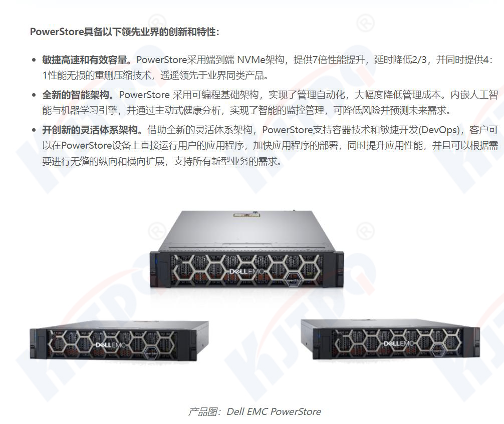
(1)Computing power storage system EMC
First of all, EMC has made many adjustments to the VNX series management interface to make it more interactive, clear, simple, and easy to operate. Like mainstream storage vendors, the interface uses a Java-based Web UI (user interface), which EMC calls USM (Unisphere Service Manager) to manage the array.
(2)Computing power system
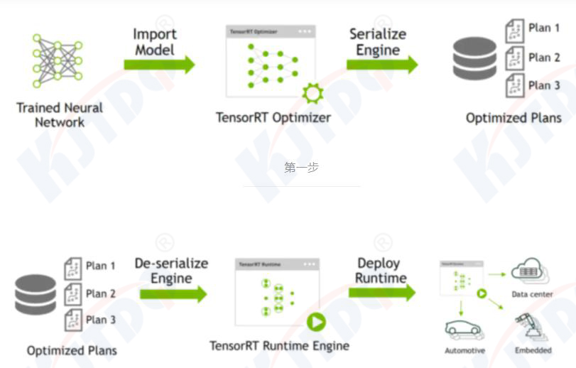
High throughput, low response time, low resource consumption and simple deployment process requirements, therefore TensorRT is a deployment-level solution to solve the challenges and impacts of inference. TensorRT was developed by nvidia itself. Its main function is to optimize the algorithm and then deploy it as shown below.
NVIDIA dedicated inference chip:
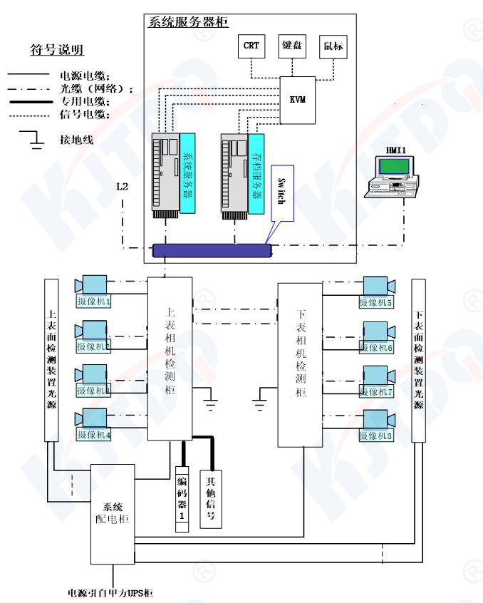
This system will integrate mechanical modules, light sources, imaging equipment, detection components, computer modules and three electrical equipment. In order to ensure that various types of equipment are seamlessly connected and complete setting functions, electrical integration will use special interface equipment to ensure the stability and reliability of long-distance, high-speed, and massive image data transmission; special optical fibers, high-speed 10G network ports, optical cables and The connection equipment ensures the data connection between image acquisition equipment such as cameras and surface detection components; the special power cable design for the light source ensures the effectiveness of long-distance power transmission between the on-site installation position and the constant current device in the power distribution control cabinet; ensures that the detection components are Universal server data communication connection.
In the detection system, the mechanical mechanism mainly plays the role of protective support, protection and precision adjustment. The mechanical mechanism must have sufficient stiffness, strength, and shock resistance, and must have a temperature control function. In addition, in order to meet the imaging light path requirements and obtain the best imaging effect, the camera and light source must be accurately adjustable. Key hardware includes CMOS image sensors and lenses, photoelectric converters, and lighting sources. In order to ensure the safety and normal operation of these devices, The mechanical mechanism is required to have protective functions to prevent oil and steam pollution. To meet the above requirements.
1.Image fine-tuning module
2.Organization layout diagram
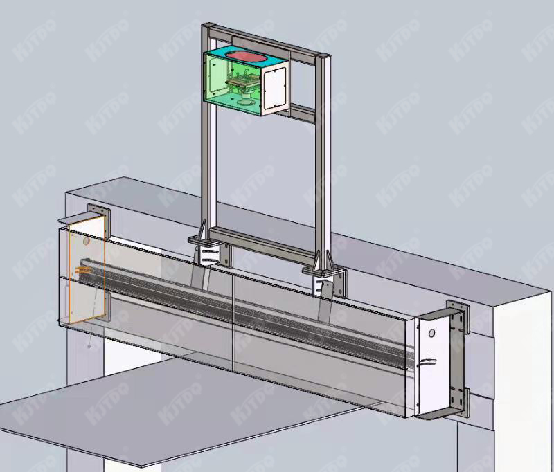
(1) General organizational structure
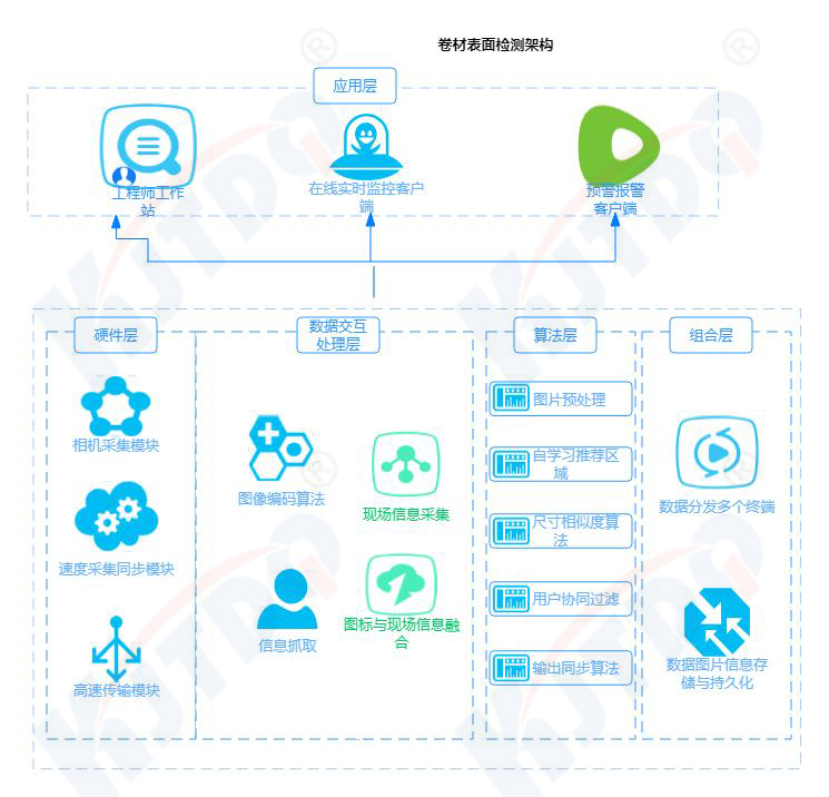
(2) Simple function introduction composition
(2).1real time picture
Display the real-time running picture of the steel coil and display the identified defects.
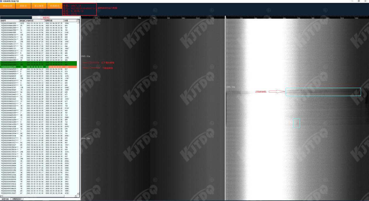
(2).2Steel coil review
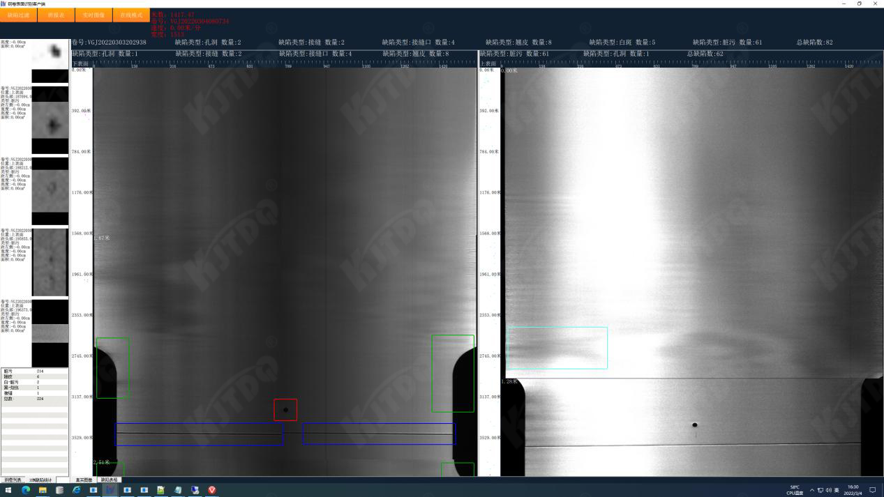
(2).3 Online and offline modes
Online mode: display real-time picture and steel coil list.
Offline mode: Do not display the real-time picture and display the steel coil list.
Operation skills: When the real-time picture is displayed, if you need to review the latest steel coil, you can click to enter the offline mode and no longer receive the real-time picture, so as to facilitate viewing of the latest steel coil.
(2).4 steel coil download
Right click on Download to download all images of steel coils. The download path is in the client execution directory and the Steels subdirectory.
During the download process, a progress bar will display the download progress.
(2).5 board report
Statistics of the number of steel coils, number of defects and other information in a period of time.
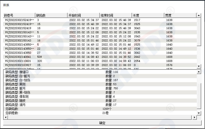
(2).
6 Defect filtering and alarming
Filter defects that do not meet the conditions and issue alarms for specified defects, etc.
Multiple configurations are independent of each other, as long as one configuration condition is met.
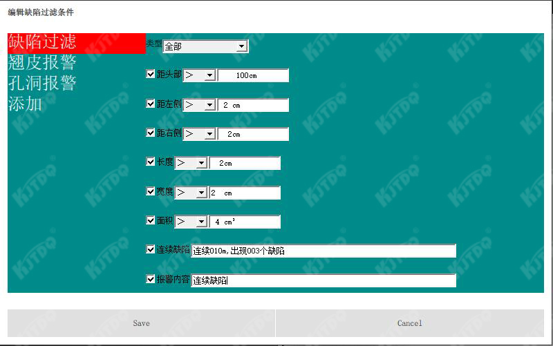

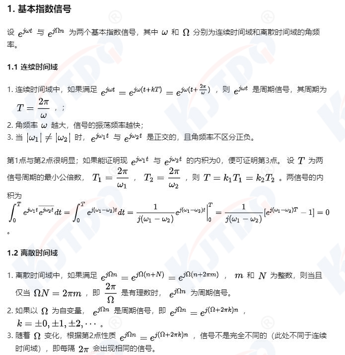
Fourier transform processing pictures
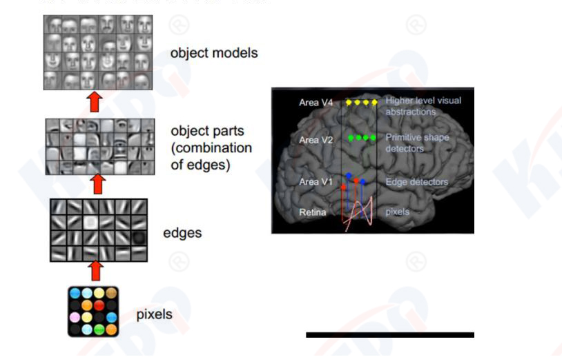
The principle of human vision is as follows: starting with raw signal intake (pupil intake of pixels), then preliminary processing (some cells in the cerebral cortex find edges and directions), and then abstraction (the brain determines that the shape of the object in front of you is a circle). shape), and then abstract it further (the brain further determines that the object is a balloon). Here is an example of face recognition performed by the human brain:
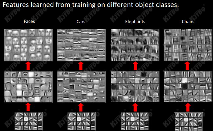
We can see that the features at the lowest level are basically similar, that is, various edges. The higher up, the more features (wheels, eyes, torso, etc.) of such objects can be extracted. At the top level, different high-level features can be extracted. The features are finally combined into corresponding images, allowing humans to accurately distinguish different objects.
Then we can naturally think: Can we imitate this characteristic of the human brain and construct a multi-layer neural network? The lower layer recognizes primary image features, and several low-level features form higher-level features, and finally through multiple levels What about the combinations and finally classification at the top level? The answer is yes, and this is the inspiration for many deep learning algorithms, including CNNs.
Introduction to convolutional networks
Convolutional neural network is a multi-layer neural network that is good at processing machine learning problems related to images, especially large images.
Through a series of methods, the convolutional network successfully reduces the dimensionality of image recognition problems with huge amounts of data, and finally enables it to be trained. CNN was first proposed by Yann LeCun and applied to handwritten font recognition (MINST). The network proposed by LeCun is called LeNet, and its network structure is as follows:

This is the most typical convolutional network, consisting of a convolution layer, a pooling layer, and a fully connected layer. The convolution layer cooperates with the pooling layer to form multiple convolution groups, extract features layer by layer, and finally complete the classification through several fully connected layers.
The operations performed by the convolutional layer can be considered to be inspired by the concept of local receptive fields, while the pooling layer is mainly to reduce the data dimension.
To sum up, CNN simulates feature distinction through convolution, reduces the order of magnitude of network parameters through convolution weight sharing and pooling, and finally completes tasks such as classification through traditional neural networks.
training process
The training process of convolutional neural network is similar to that of traditional neural network, and also refers to the back propagation algorithm.
The first stage, forward propagation stage:
a) Take a sample (X, Yp) from the sample set and input X into the network;
b) Calculate the corresponding actual output Op.
At this stage, information is transferred from the input layer to the output layer through step-by-step transformation. This process is also what the network performs when it is running normally after completing training. During this process, the network performs calculations (actually, the input is multiplied by the weight matrix of each layer to obtain the final output result):
Op=Fn(…(F2(F1(XpW(1))W(2))…)W(n))
The second stage, backward propagation stage
a) Calculate the difference between the actual output Op and the corresponding ideal output Yp;
b) Back propagate the adjustment weight matrix by minimizing the error.
The strip surface quality online detection system is closely related to the basic interface of the production line. The power supply and distribution of the detection system, the cooling of the protection box, and the starting and stopping of the detection software, distinguishing sub-volumes, and locating defects are all closely related to this.
| serial number | project | Specific requirements | Remark |
| 1 | System power supply and distribution (meter inspection) | 220V 32A | |
| Multi-function detector (if needed) | 220V 32A | ||
| 2 | Roll change signal | Welding seam signal (switch value) | IO interface |
| 3 | speed signal | HTL/TTL | Steering roller motor encoder signal |
Due to changes in the rolling speed of the production line, it is necessary to access the strip speed signal as an external trigger signal for the camera to ensure that the camera acquisition speed is synchronized with the strip movement speed and is not affected by changes in strip speed. The captured image can maintain a constant The resolution can also ensure the accuracy of strip length measurement and defect location.
For a strip surface quality online inspection system, a signal is needed to inform the system of the arrival of a new roll, which serves as the starting point for counting the length of the new roll and the positioning basis for the position of the defect distance from the head.
Generally speaking, the start detection signal needs to be sent to the detection system earlier than the strip head reaches the detection position. The signal from a weld detector or hot metal detector in front of the detection position is often selected.
In order to ensure that the strip head can be accurately positioned, after knowing the actual distance between the starting signal and the detection point, the head position of the upper and lower surfaces of the strip can be corrected through appropriate system settings.
For the detection system arranged at the exit position, by accessing the cutting signal (final cut/first cut + final cut), the detection data can be stored as the exit volume number. With appropriate system configuration and processing logic, multiple on-site Various process changes, such as sampling, scrap cutting, upper/lower coiling, etc., are individually defined during storage.
Accurate export roll inspection data facilitates users of this unit and subsequent processes to query defect information and meets the requirements for long-term accurate traceability of inspection data.


