check

check

check

check
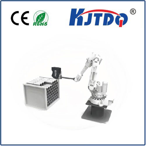
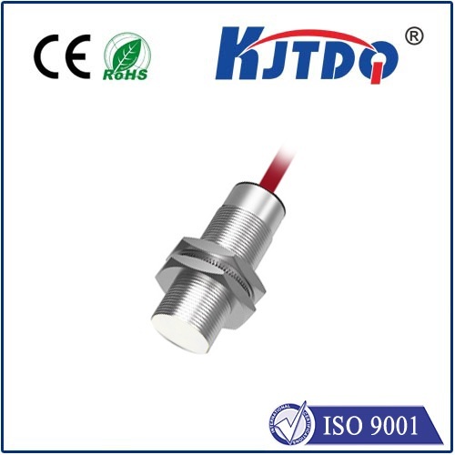
Kjt TLS laser ranging sensor can detect vertical or tilted targets within a range of 30 meters, regardless of color, material or gloss.
•Over-limit relay output, supports NPN/PNP; voltage and current analog output; RS485 output
•Excellent combination of range, repeatability and accuracy enables highly reliable target detection and precise distance measurement
• Five 8-segment displays and push button programming for easy installation, troubleshooting and real-time distance measurement
•Durable IP67 housing, high immunity to ambient light interference and stable performance over a wide range of temperatures provide reliable performance in challenging environments


KJT-TLS Detailed technical parameters
| model | Adjustable range | Input/output parameters |
| KJT-TLS-01C-A1 | 0-1M Adjustable | Input:Voltage10-30VDC(±10%) output:Analog quantity all the way(0-10V),One switch value |
| KJT-TLS-01C-A2 | 0-1M Adjustable | Input:Voltage10-30VDC(±10%) output:Analog quantity all the way(4-20MA ),One switch value |
| KJT-TLS-01C-A3 | 0-1M Adjustable | Input:Voltage10-30VDC(±10%) output:Analog quantity all the way(4-20MA )+485 |
| KJT-TLS-01C-A4 | 0-1M Adjustable | Input:Voltage10-30VDC(±10%) output:2-way switch |
| KJT-TLS-05C-B1 | 0-5M Adjustable | Input:Voltage10-30VDC(±10%) output:Analog quantity all the way(0-10V),One switch value |
| KJT-TLS-05C-B2 | 0-5M Adjustable | Input:Voltage10-30VDC(±10%) output:Analog quantity all the way(4-20MA ),One switch value |
| KJT-TLS-05C-B3 | 0-5M Adjustable | Input:Voltage10-30VDC(±10%) output:Analog quantity all the way(4-20MA )+485 |
| KJT-TLS-05C-B4 | 0-5M Adjustable | Input:Voltage10-30VDC(±10%) output:2-way switch |
| KJT-TLS-10C-C1 | 0-10M Adjustable | Input:Voltage10-30VDC(±10%) output:Analog quantity all the way(0-10V),One switch value |
| KJT-TLS-10C-C2 | 0-10M Adjustable | Input:Voltage10-30VDC(±10%) output:Analog quantity all the way(4-20MA ),One switch value |
| KJT-TLS-10C-C3 | 0-10M Adjustable | Input:Voltage10-30VDC(±10%) output:Analog quantity all the way(4-20MA )+485 |
| KJT-TLS-10C-C4 | 0-10M Adjustable | Input:Voltage10-30VDC(±10%) output:2-way switch |
| KJT-TLS-20C-D1 | 0-20M Adjustable | Input:Voltage10-30VDC(±10%) output:Analog quantity all the way(0-10V),One switch value |
| KJT-TLS-20C-D2 | 0-20M Adjustable | Input:Voltage10-30VDC(±10%) output:Analog quantity all the way(4-20MA ),One switch value |
| KJT-TLS-20C-D3 | 0-20M Adjustable | Input:Voltage10-30VDC(±10%) output:Analog quantity all the way(4-20MA )+485 |
| KJT-TLS-20C-D4 | 0-20M Adjustable | Input:Voltage10-30VDC(±10%) output:2-way switch |
| KJT-TLS-30C-E1 | 0-30M Adjustable | Input:Voltage10-30VDC(±10%) output:Analog quantity all the way(0-10V),One switch value |
| KJT-TLS-30C-E2 | 0-30M Adjustable | Input:Voltage10-30VDC(±10%) output:Analog quantity all the way(4-20MA ),One switch value |
| KJT-TLS-30C-E3 | 0-30M Adjustable | Input:Voltage10-30VDC(±10%) output:Analog quantity all the way(4-20MA )+485 |
| KJT-TLS-30C-E4 | 0-30M Adjustable | Input:Voltage10-30VDC(±10%) output:2-way switch |
Electronic parameters
| Supply voltage UV | DC 10V...30V |
| residual ripple | ≤ 5 V |
| Power consumption | ≤ 2.1W 4) |
| initialization time | ≤ 250ms |
| Preheat time | ≤ 10s |
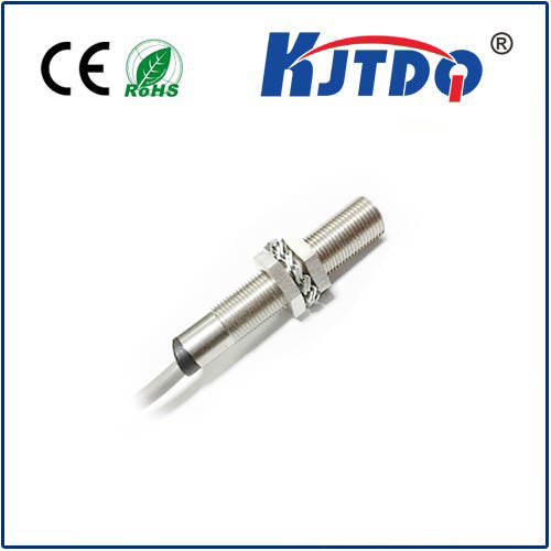
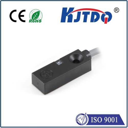
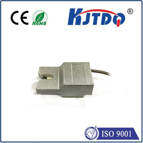
| Shell material | Aluminum alloy(AL) plexiglass(PMMA) |
| Connection Type | M12 Waterproof connector, lead wire |
| monitor | 5-digit digital tube, 5 x LED |
| weight | 360g |
| Enclosure rating | IP65 |
| Protection level | III |
1) Limit value, reverse polarity protection when operating in a circuit with short-circuit protection: Suitable for max. 8 A.
2) For TLS-xxxx: UV > 15 V.
3) Must not fall below or exceed UV tolerance.
4) No load.
performance
| Measuring range | 0-5M ,0-10M,0-15M ,0-20M,0-30M |
| measuring objects | natural objects |
| resolution | 1mm |
| Accuracy | Accuracy1.5 mm+d 0.5‰ |
√ The measuring range can be set, suitable for up to 30 meters
√ Digital tube displays measurement results in real time
√ LED status display
√ Voltage analog output
√ Over-limit relay output (supports NPN/PNP)
√ Measurement distance correction
√ Basic parameter settings
√ RS485 interface, supports Modbus RTU protocol.
√ RS485 interface, supports Modbus RTU protocol.
| frequency | 5Hz,10Hz, 20Hz, 30Hz |
| Output time | ≥ 4 ms 6) |
| light source | red laser |
| Laser level | 1 (IEC 60825-1:2014, EN 60825-1:2014) 7) |
| Typical photoelectric size distance(mm) | 15 mm x 15 mm (10 m) |
| Other functions | Settable sliding average: fast/slow, Switching mode: Distance Object (DtO), Teachable, parameterizable and invertible digital output, Adjustable hysteresis, Teachable, parameterizable, reversible analog output terminal, multi-function input: laser off/external teaching/disable, turn off the display, restore factory settings, lock user interface |
| Average laser service life(25℃ ) | 100,000 h |
1) Corresponds to 1 σ.
2) 6% ... 90% reflectivity.
3) Depends on how the average is formed: fast/slow.
4) 90% reflectivity.
5) Introduce the object into the measurement range from the side.
6) Continuously changes the distance to the object within the measuring range.
7) Wavelength: 658 nm; suitable for high power: 120 mW; pulse duration: 2.5 ns; contact rate: 1/400.
interface
| digital output | ||
| quantity | 1 1) 2) 3) | |
| type<, /SPAN> | PNP,NPN optional | |
| Suitable for large output currentIA | ≤100 mA | |
| Analog output | ||
| quantity | 1 | |
| type | Voltage/current output optional | |
| Voltage and current | 0V-10V/4mA-20mA,≤300Ω | |
| resolution | 12bit | |
| Multi-function input(MF) | 1 x3) 4) | |
| lag | 10mm...1000mm |
Environmental parameters
| Operating environment temperature | –15 °C ... +50 °C |
| Storage environment temperature | –20 °C ... +60 °C |
| Suitable for high relative air humidity (non-condensing) | ≤ 85 % |
| Type resistance to ambient light | 40,000 lx |
| Vibration resistance | EN 60068-2-6, EN 60068-2-64 |
| Impact resistance | EN 60068-2-27 |
Instructions for use
The user interaction interface of this product mainly consists of digital tubes, LED indicators and buttons. Digital tubes and LED indicators are used to display product information, and buttons are used to modify product parameters.

This product has 5 LED lights to display the basic status of the product. See the table below for detailed instructions.
| 名称 | 作用 | 描述 |
| RUN | 指示激光传感器运行状态 | LED闪烁,表明激光传感器正在处于运行中 |
| OUT | 指示越限继电器输出状态 | 当发生越限事件时继电器驱动输出,该LED灯亮起;没有越限事件时该灯熄灭 |
| MAX | 指示测量结果是否超出量程 | 当测量结果超过量程时,MAX灯亮 |
| MIN | 测量结果是否小于0 | 当测量结果为负数时,MIN灯亮 |
| PRO |
| 1. 用户进入配置界面,PRO灯常亮,配置完成进入主界面PRO灯熄灭; 2. 如果产品出现异常PRO灯闪烁 |
button
This product has a total of 3 physical buttons. By short pressing and long pressing, six virtual buttons are created, namely up, down, left, right, confirm, and return.
| physical buttons | Short press | Long press | Location |
| button1(ENTER/ESC) | confirm | return | Fits left side |
| button2(UP/LEFT) | up | left | middle |
| button3(DOWN/RIGHT) | down | right | Fits right side |
Notice:
1. The corresponding event will be triggered only after the button is pressed and released.
2. A short press means pressing for 0.2~0.5 seconds and then releasing it; a long press means pressing for more than 0.5 seconds and then releasing it.
This product has five 8-segment digital tubes as the display interface. The digital tubes can display numbers and English letters, and can be used in conjunction with the buttons to complete the functions of product information display and parameter setting. Please refer to Appendix A for the display effect of the digital tube.
Figure 1 shows the basic interface operation process of the product.
After the product is powered on, it enters the main interface by default and displays the current measurement results in real time. When ENTER is pressed, the menu selection interface is entered; in the menu selection interface, use the up and down buttons to switch submenus, and press ENTER to enter the corresponding submenu interface. Press the ESC button on the menu selection interface to return to the main interface.
In the submenu interface, after using the up, down, left and right buttons to modify the parameters, press ENTER or ESC to return to the menu selection interface (if you press ENTER to save the modification, if you press ESC to undo the modification).

The main interface is the measurement result display interface, which displays the current measurement result in meters with 3 decimal places.
The main interface is displayed by default after power-on. Press ENTER to switch to the menu selection interface. Press ESC on the menu selection interface to switch back to the main interface.
Zero correction
In the menu selection interface, use the up and down keys to select CALIB, and press ENTER to enter the zero calibration interface. At this time, the interface displays the corrected data. By adjusting the calibration value, the interface updates the correction data in real time.
Fix the product on the test rail through the positioning hole, and place obstacles at a certain distance (such as 1 meter) from the positioning hole. Use the up, down, left and right buttons to modify the calibration value so that the data displayed on the interface is the same as the actual distance (for example, 1 meter). The up and down keys increase or decrease the calibration value; the left and right keys modify the amplitude of the increase or decrease of the calibration value, and the modified number will be prompted by flashing.
After the calibration is completed, pressing ENTER will display the data currently used for calibration. At this time, you can also use the up, down, left and right buttons to adjust the correction data, the method is the same as above. After pressing ENTER again, the zero position calibration will be completed; if ESC is pressed, the modification will be canceled and the menu selection interface will be returned.
In order to cope with different application scenarios, this product supports the following 4 sampling modes.
Slow mode is used to accurately measure the distance to stationary objects, characterized by high accuracy and slow response speed; fast mode is used to measure fast-moving objects, characterized by fast response speed and reduced measurement accuracy.
| Sampling mode | Data sampling frequency | Calculate the amount of data used |
| slow(1.SLOW) | 5Hz | 8 |
| normal(2.NORM) | 10Hz | 8 |
| Quick 1(3.FST1) | 20Hz | 4 |
| Quick 2(4.FST2) | 30Hz | 2 |
This product supports relay over-limit alarm output. Set the normal working range of the product by setting the working mode; when the measurement result exceeds the normal range, the drive relay will act.
| Operating mode | Lower limit of normal range | upper limit of normal range |
| Mode 1(1.mod1) | 0 | Limit 3Limit3) |
| Mode 2(2.mod2) | Limit 2(Limit2) | Limit 3(Limit3) |
| Mode 3(3.mod3) | (limit1+limit2)/2 | (limit2+limit3)/2 |
Working mode description

In the menu selection interface, select to enter the working mode setting interface, select the required working mode through the up and down keys, and press ENTER to confirm the modification. If you want to undo the modification, press ESC to return directly to the menu selection interface.
Note: 1.limit1, limit2, limit3 must be set in order from small to large, limit3 is suitable for large, limit1 is suitable for small
2. If limit1, limit2, and limit3 are not set in ascending order, they will be reordered when calculating the range.
Select from the menu selection interface to enter the limit setting interface. There are three limit parameters that can be set. Which limit parameters to set are determined according to the working mode.
The setting of limit parameters is divided into two stages: initial value selection stage and fine-tuning stage.
Initial value selection stage
The initial value of the limit parameter can be obtained from three sources: system configuration, current measurement result, zero
Enter the limit setting interface from the menu selection interface, which displays the current measurement results. At this time, directly press ENTER, select the system configuration as the initial value of fine-tuning and enter the fine-tuning stage; press the up key (or left key) to use the current measurement result as the initial value of fine-tuning and enter the fine-tuning stage; press the down key (or right key) ) Set zero as the initial value of fine-tuning and enter the fine-tuning phase
。
fine-tuning phase
In the limit fine-tuning stage, use the up and down keys to adjust the limit size, and use the left and right keys to change the fine-tuning amplitude.
After fine-tuning is completed, press ENTER to save the changes and return to the menu selection interface. Press ESC to undo the modification and return to the menu selection interface. If you still need to set the limit value at this time, press ENTER in the menu to enter the initial value selection stage again, and complete the subsequent operations.
This product can be set to different measuring ranges according to needs. Currently supported measuring ranges are 1m, 3m, 5m, 10m, 15m, 20m and 30m. The full scale of the analog output corresponds to 10V output, and 0m corresponds to 0V output.
In the menu selection interface, select to enter the range setting interface, and use the up and down keys to select different ranges. Press ENTER to save changes and return to the menu selection interface; press ESC to undo changes and return to the menu selection interface.
In the menu selection interface, select to enter the factory reset interface, and use the up and down keys to switch between YES and NO. When YES is selected, pressing ENTER will restore the factory default configuration and return to the menu selection interface; when NO is selected, pressing ENTER or ESC will directly return to the menu selection interface.
Through the following steps, you can quickly get started with this product.
1. Range setting
2. Zero calibration
3. Set sampling mode
4. Set working mode and limits
5. Install test voltage analog output and relay drive output
● Measure the length, width, thickness and position of various plates, such as steel plates, medium plates, rubber plates, plastic plates, etc.
● Measure the accurate position of bulk solids, liquids, anti-corrosion materials, and radiation objects in various containers and large tanks.
● Measure the position of various moving objects, especially objects moving on rails, such as cranes and rail transport vehicles.
● Bridge static deflection online (wireless) monitoring system
● Tunnel overall deformation online (wireless) monitoring system, tunnel key point deformation online (wireless) monitoring system
● Balance monitoring system
● Thickness and size monitoring system
● Mine elevator, large hydraulic piston height monitoring, positioning monitoring system
Appendix A: Example of digital tube display effect

Appendix B: 485 communication protocol
This product has a reserved RS485 interface and supports the Modbus RTU protocol to read sensor data in real time, and the product configuration can also be modified.
The default baud rate is 9600bps, 8 data bits, 1 stop bit, and no parity.
| No. | address | content | illustrate | Order |
| 1 | 0x0000 | Product number | Product model code | 03,04 |
| 2 | 0x0008 | Hardware version number | BCD code, such as 0x0101, the hardware version is V1.0.1 | |
| 3 | 0x0009 | Software version number | BCD code, such as 0x0110, the hardware version is V1.1.0 | |
| 4 | 0x0010 | Modbus address | Modbus communication address, default is 0x01 | 03 |
| 5 | 0x0011 | baud rate | Use baud rate/100, for example, 96 means the baud rate is 9600bps | |
| 6 | 0x0012 | data bits | 8 or 7 | |
| 7 | 0x0013 | Stop bit | 1 or 2 | |
| 8 | 0x0014 | check | 0 means no parity, 1 means odd parity, 2 means even parity. | |
| 9 | 0x0020 | Current measured distance | Unit mm | 03,04 |
| 10 | 0x0030 | Measuring range | Unit meter, support1、3、5、10、15、20、30 | 03,06/16 |
| 11 | 0x0031 | Operating mode | Supports 1-3, corresponding to working mode 1, working mode 2, and working mode 3 respectively. | |
| 12 | 0x0032 | Sampling mode | Supports 1-4, corresponding to slow, normal, fast 1, fast 2 respectively | |
| 13 | 0x0033 | Limit 1 | Unit mm | |
| 14 | 0x0034 | Limit 2 | ||
| 15 | 0x0035 | Limit 3 | ||
| 16 | 0x0040 | Zero calibration | Write 0x0001 to use the current measurement data for zero calibration | 06 |
| 17 | 0x0041 | reset | Write 0x0001 to restore factory settings | 06 |
Modbus command description
03: Read the holding register value 04: Read the input register value 06: Write a single holding register value 16: Write multiple holding register values