check

check

check

check
Title: Understanding Up Limit Switches: A Comprehensive Guide
Introduction to Up Limit Switches
In industrial automation and control systems, up limit switches are essential components that help to prevent the equipment from over-speeding or over-loading. These devices are designed to detect the upper limit of the machine's movement and shut down the system when it reaches that point. Up limit switches come in different forms, including contact sensors, magnetic switches, and photoelectric switches. In this article, we will explore the working principle, types, and installation of up limit switches in detail.
Working Principle of Up Limit Switches
Up limit switches operate based on the principle of resistance. When the switch is closed, there is a continuous flow of electrical current between the contacts, which results in resistance buildup. As the machine moves past the switch, the contact opens, and the resistance drops. This change in resistance triggers an alarm or signal that alerts the control system to stop the equipment. The exact mechanism depends on the type of switch used.

Types of Up Limit Switches
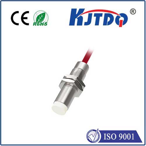
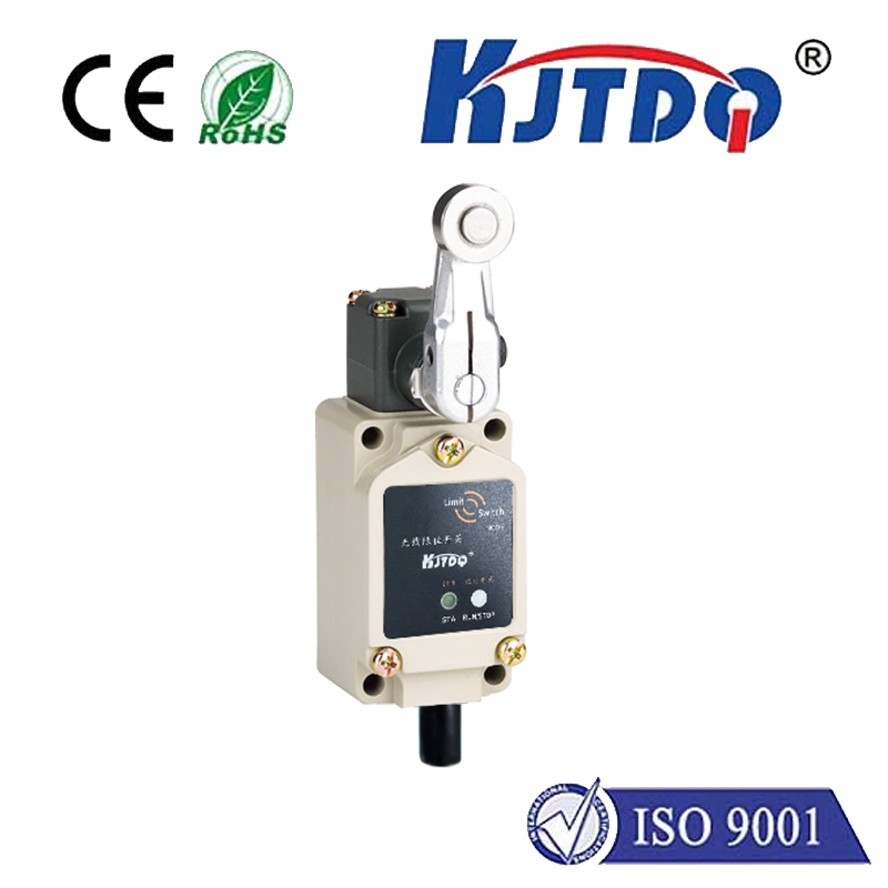
1. Contact Switches: These are the most common type of up limit switches found in industrial automation systems. They consist of two metal contacts that are brought into contact when the switch is closed. The contact provides a path for current flow when the switch is open. Contact switches are available in different configurations, including single-pole or double-pole designs, and can be operated with either mechanical or electronic means.
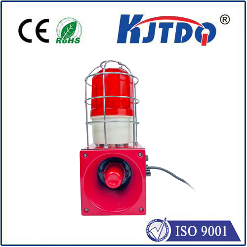
2. Magnetic Switches: These switches use a magnetic field to detect motion and trigger an alarm or signal. When the switch is closed, a magnetic field is generated that causes a magnetic arm to move towards the contacts, completing the circuit. Once the arm reaches the contacts, they close, cutting off the flow of current and triggering the alarm or signal. Magnetic switches are typically used in applications where space is limited or where mechanical components are not desired.
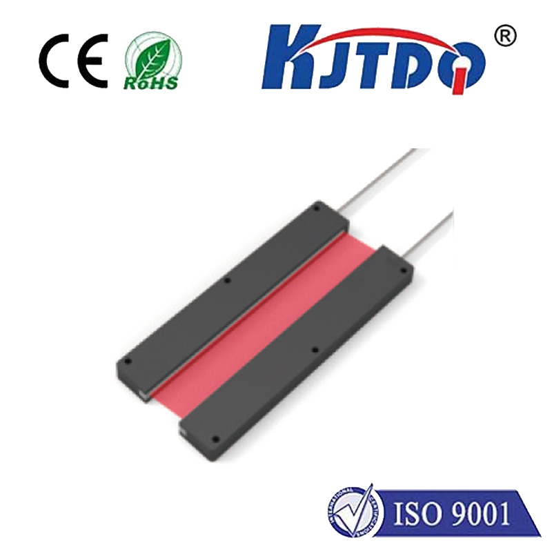
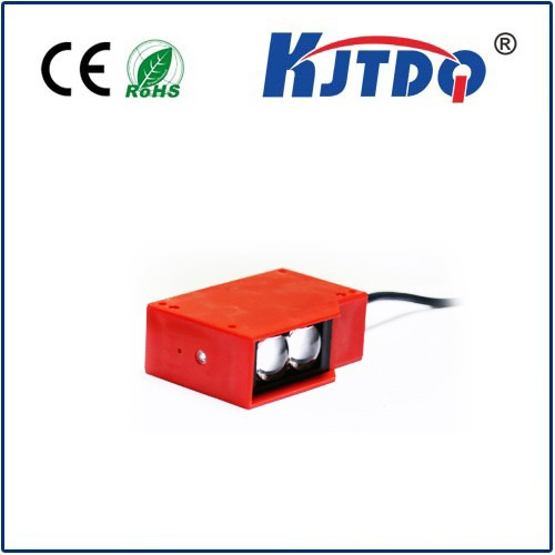
3. Photoelectric Switches: These switches work by detecting changes in light intensity caused by movement or rotation of an object. When an object passes through the light source, it blocks part of the light, causing a change in light intensity that is detected by the switch. Photoelectric switches are commonly used in applications where precise detection of motion is required, such as in robotics and automotive systems.
Installation of Up Limit Switches
Up limit switches must be installed in a location that provides clear visibility of the motion they will monitor. The switch should be positioned to allow for proper alignment with the machine's travel path. The exact placement will depend on the specific application and requirements.
Once installed, up limit switches should be wired according to the control system's wiring diagram. The electrical connection should be made using appropriate terminals or connectors to ensure proper functionality and safety. It is important to follow all safety guidelines and regulations when working with electrical components.
Conclusion
Up limit switches play a critical role in ensuring safe and efficient operation of industrial automation systems. By understanding their working principles, types, and installation requirements, engineers and technicians can effectively design and install up limit switches to meet specific needs and enhance overall system performance.