English


check

check

check

check

check
check
check
check
check
check
Title: Understanding Pin Type Limit Switches for Improved Control Efficiency
Introduction:
In industrial automation and control systems, limit switches are an essential component that helps to prevent equipment from excessive or reverse motion. Pin type limit switches are one of the most commonly used types, with their simple mechanism making them reliable and cost-effective. This article aims to provide an in-depth understanding of pin type limit switches, including their structure, working principle, installation, and usage tips to enhance control efficiency.
Section 1: Pin Type Limit Switches: Structure and Working Principle
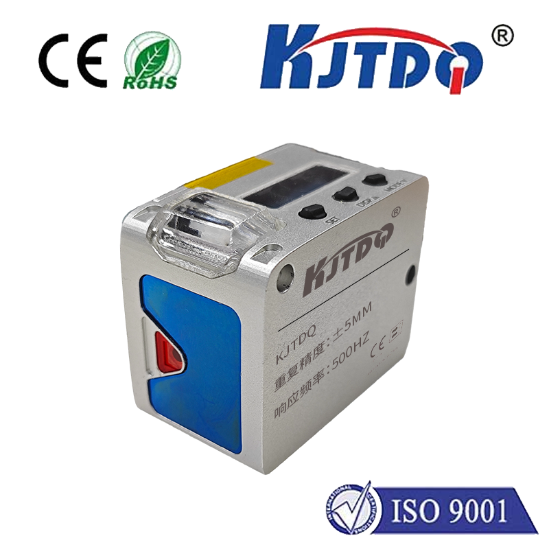
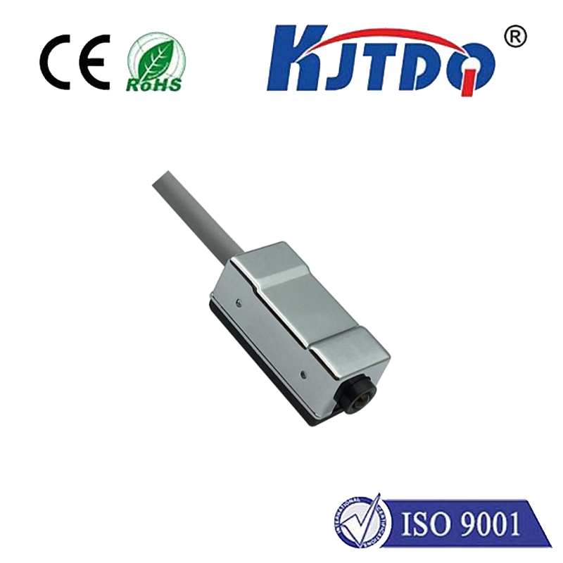
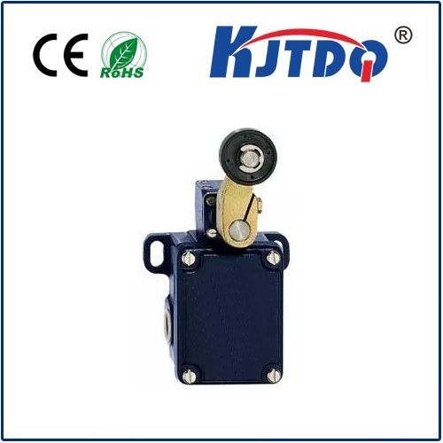
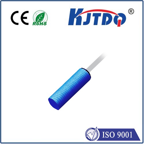
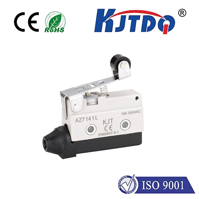
A pin type limit switch is a mechanical device that consists of a movable plunger, a set of contacts, and a receptacle or socket. The plunger is attached to a spring that allows it to move up or down within the contact assembly. When the plunger reaches the upper or lower limit of the contact assembly, it stops moving, causing a signal to be generated.
The working principle of a pin type limit switch is based on the concept of contact opening. When the movable plunger comes into contact with the contacts, it closes a circuit, allowing current to flow through it. If the plunger falls beyond the contact limit, the circuit is broken, and no current flows. This action generates a signal indicating whether the switch has been triggered or not.
Section 2: Installation of Pin Type Limit Switches
Proper installation is crucial for ensuring the effective functioning of pin type limit switches. Here are some key steps to follow:
1. Choose a suitable location for the switch: The switch should be installed in a position where it can detect the movement of the equipment being controlled accurately. It should be placed close to the axis of rotation or vibration to avoid false triggering.
2. Determine the correct orientation: The switch should be installed with the contact faces facing in the same direction as the desired direction of operation (up or down). The direction of travel should also be considered when installing the switch.
3. Ensure proper wiring: The wiring of the switch should be done according to the manufacturer's instructions. The input and output wires should be connected appropriately to ensure proper communication between the switch and the control system.
4. Test the switch before installation: Before finalizing the installation, it is essential to test the switch to ensure it works correctly. This includes checking the trigger distance, sensitivity, and reliability of the switch.
Section 3: Best Practices for Using Pin Type Limit Switches
To optimize control efficiency and prevent damage to equipment, it is important to follow some best practices when using pin type limit switches:
1. Regular maintenance: Keep the switch clean and free from debris to ensure accurate detection and reliable operation. Also, check the contacts regularly for signs of wear or damage and replace them if necessary.
2. Avoid misalignment: Make sure that the switch is aligned correctly to avoid false triggering or missed triggers. Misalignment can lead to inconsistent control signals and potential damage to equipment.
3. Monitor switch activity: Regularly monitor the switch activity to identify any unusual patterns or behavior that may indicate issues with equipment performance or safety concerns. Address these issues promptly to prevent further complications.
4. Consider environmental factors: The operating environment can impact the performance of pin type limit switches. Factors such as temperature, humidity, and vibration must be considered when selecting and installing switches to ensure reliable operation under different conditions.