English


check

check

check

check

check
check
check
check
check
check
Title: Understanding Limit Switches in Hydraulic Systems
Introduction to Limit Switches in Hydraulic Systems
Hydraulic systems are widely used in various industries, from manufacturing to construction, for their ability to control the flow of fluid and power. One critical component of these systems is the limit switch, which plays a crucial role in ensuring safety and efficient operation. In this article, we will explore what limit switches are, their function in hydraulic systems, and some common types.
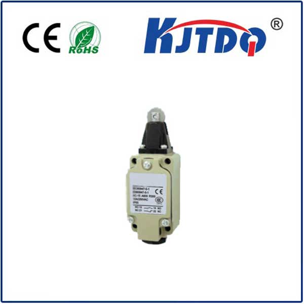
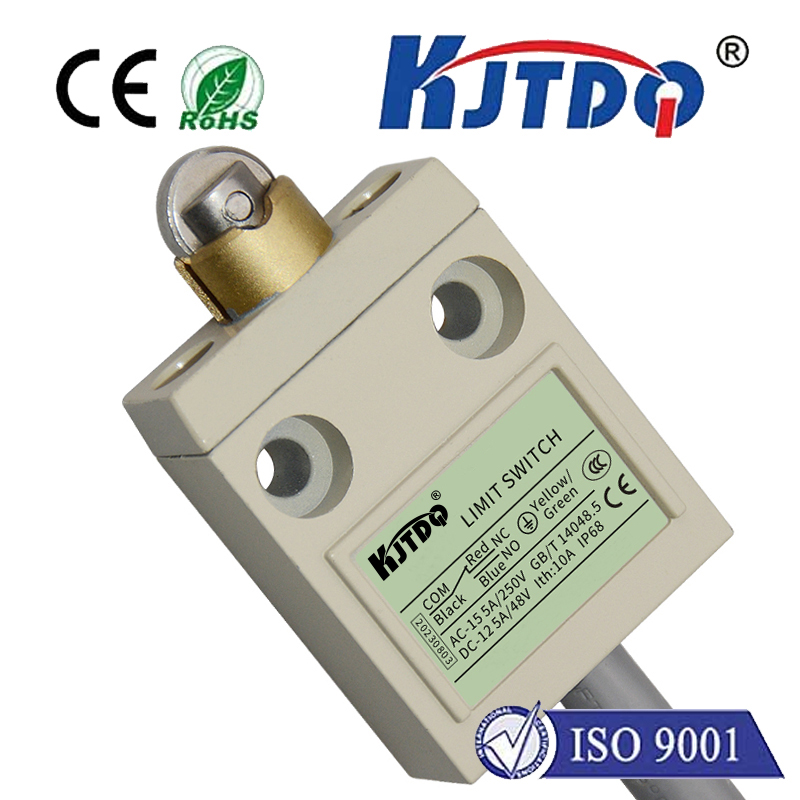
What are Limit Switches?
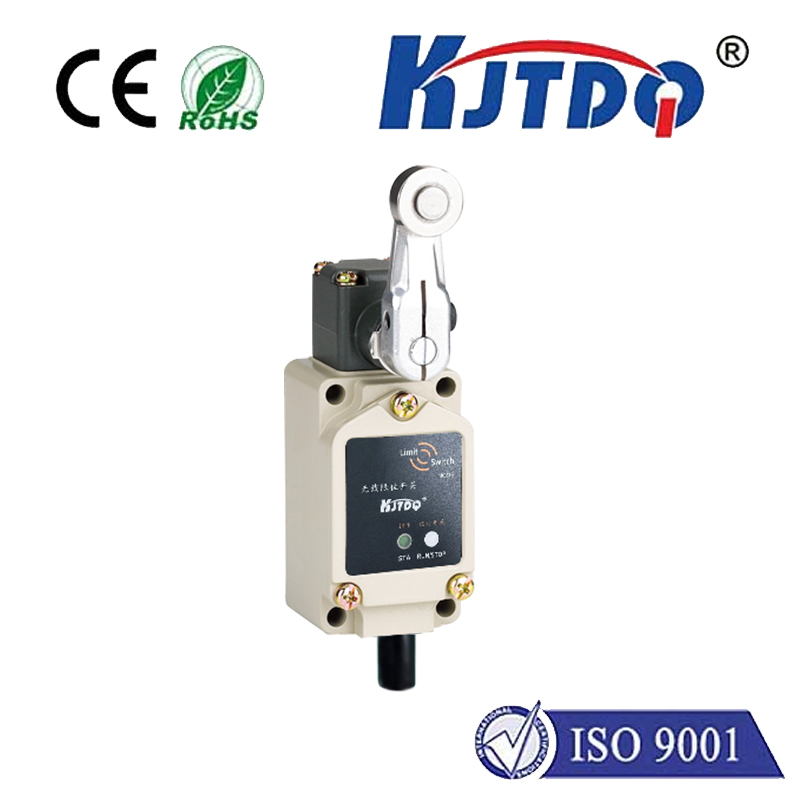
A limit switch is a mechanical component that detects the presence or absence of an object, typically a lever or button, and sends a signal to an operator or control system. The term "limit" refers to the range within which the switch operates. When the switch is activated, it opens or closes a circuit, allowing fluid to flow through the system or blocking it.
Function of Limit Switches in Hydraulic Systems
Limit switches in hydraulic systems are designed to protect both the system and operators from damage. They help ensure that hydraulic fluid does not exceed a predetermined pressure or flow rate, preventing overpressure or overloading of components such as valves, pistons, and cylinders. This can lead to component failure, costly repairs, or even injury.
Limit switches also assist in maintaining proper system alignment and positioning. By detecting the position of a lever or button, the switch can send signals to the control system, ensuring that hydraulic components move smoothly and predictably. This reduces the likelihood of accidents caused by misalignment or improper functioning of components.
Types of Limit Switches
There are several types of limit switches available for use in hydraulic systems, each with its specific features and applications. Some of the most common types include:
1. Travel-type limits: These switches consist of a movable lever or disc that can move up or down a travel distance when activated. They are commonly used for positioning devices such as rams and indexers.
2. Proximity limits: These switches operate on the principle that an object must physically touch a sensitive point before opening or closing a circuit. They are often found in proximity sensors used to detect the presence of objects like tools or parts in a workpiece.
3. Zero-position limits: These switches are designed to close a circuit when the lever reaches a certain zero position, indicating that the object has reached its intended location. They are commonly used in positioning devices that require precise alignment.
4. Sensor limits: These switches incorporate sensors into their design to provide more accurate detection of the presence or absence of an object. They are commonly used in applications where precise detection is essential, such as robotics or automation.
Conclusion
Understanding the role of limit switches in hydraulic systems is critical for ensuring safe and efficient operation of these complex systems. By selecting the appropriate type of limit switch based on their specific function and application, operators can prevent potential hazards and optimize performance.