English


check

check

check

check

check

check

check
: Precision Ranging with Light")
check

check

check
Understanding Actuator Limit Switch Schematics: A Comprehensive Guide
The actuator limit switch schematic is a crucial component in the world of automation and mechanical engineering. It plays a vital role in controlling the movement of an actuator, ensuring that it operates within safe and predefined limits. In this article, we will delve deeper into the concept of actuator limit switches, their functions, and how to interpret their schematics.
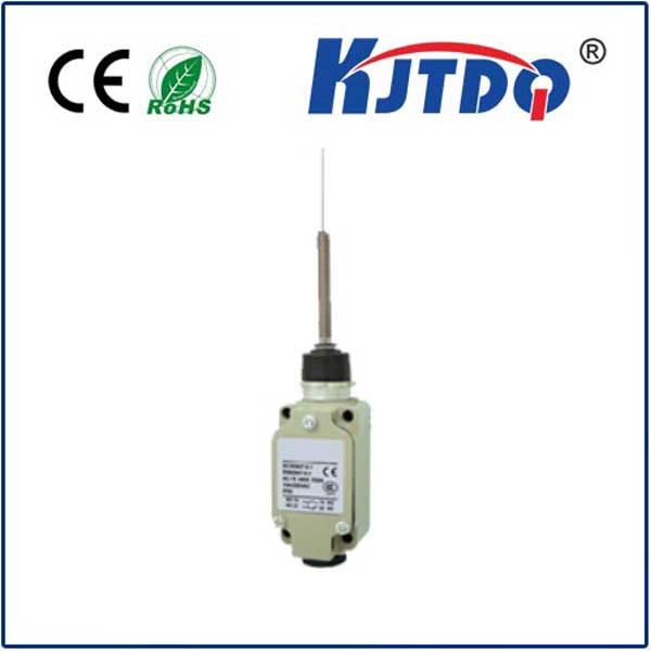
What Is an Actuator Limit Switch?
An actuator limit switch is a type of switch that is used to detect the physical position of an actuator or mechanism. It sends signals to a control system when the actuator reaches a specific point in its travel range. This information helps the control system determine whether the actuator needs to be stopped, reversed, or continued in its current direction.
Types of Actuator Limit Switches
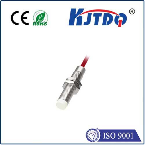
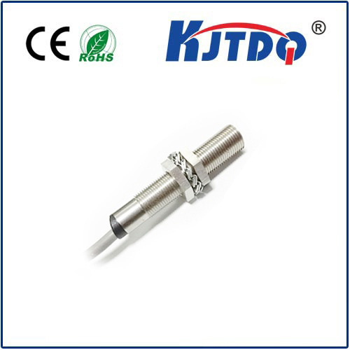
There are two main types of actuator limit switches: mechanical limit switches and electronic limit switches. Mechanical limit switches use physical contact between the actuator and the switch to trigger an electrical signal. On the other hand, electronic limit switches utilize sensors such as Hall-effect sensors, inductive proximity sensors, or capacitive sensors to detect the presence of an actuator without physical contact.
Interpreting Actuator Limit Switch Schematics
To effectively utilize actuator limit switches, it is essential to understand how to read and interpret their schematics. The schematic provides a visual representation of the wiring connections, terminal assignments, and operating principles of the limit switch. Here are some key elements to look for when analyzing a schematic:
1. Switch Type: The schematic should clearly indicate whether the limit switch is mechanical or electronic.
2. Actuator Interface: Determine how the limit switch interfaces with the actuator. This could be through direct contact, proximity sensing, or another method.
3. Control Circuitry: Understand the control circuitry connected to the limit switch. This includes any relays, solenoids, or other components that receive signals from the switch.
4. Terminal Assignments: Identify the terminal assignments on the limit switch. These may include common (C), normally open (NO), and normally closed (NC) terminals.
5. Travel Range and Direction: Determine the travel range of the actuator and the direction of movement that triggers the limit switch. This information is essential for setting up proper operation.
Applications of Actuator Limit Switches
Actuator limit switches have numerous applications in various industries, including manufacturing, robotics, material handling, and transportation. They are commonly used in machinery such as conveyors, elevators, cranes, and automated assembly lines. By monitoring the position of actuators, limit switches help ensure safe and accurate operation while preventing damage to equipment and injury to personnel.
Conclusion
In conclusion, the actuator limit switch schematic is a critical tool for understanding the functionality and operation of these essential components in automation systems. By mastering the interpretation of schematics, engineers and technicians can design, install, and maintain limit switches effectively, ensuring optimal performance and safety in various applications.